Amprobe RTD-10, User Manual
The Amprobe RTD-10 is a versatile and reliable RTD thermometer, ideal for precise temperature measurements in various applications. With its user-friendly design and advanced features, it ensures accurate readings. For detailed instructions and operational guidelines, you can easily download the free user manual from manualshive.com, enhancing your experience with this exceptional product.
Share
Download


Reviews:
No comments
Related manuals for RTD-10
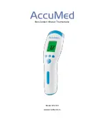
AT2103
Brand: AccuMed Pages: 14

CT100
Brand: Z-Wave Pages: 18
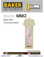
MM2
Brand: Baker Pages: 2

RT520
Brand: Salus Pages: 15

RT310SPE
Brand: Salus Pages: 2

QUANTUM SQ610RF
Brand: Salus Pages: 68

FC600
Brand: Salus Pages: 64

tekmar 562
Brand: Watts Pages: 8

Thermostat
Brand: York Pages: 8

SK-8100 Series
Brand: SATO Pages: 14

Evosense sprint Series
Brand: MMA Pages: 2

Arbonia WFS
Brand: AFG Pages: 20

DEL9000
Brand: DELEX Pages: 32

140F1080
Brand: Danfoss Pages: 16

66
Brand: Fluke Pages: 2

RC-1500
Brand: Leviton Pages: 2

TEC2101-3 N2
Brand: Johnson Controls Pages: 14

ACC-WIFI
Brand: Johnson Controls Pages: 2


