background image

PTAC

WIRELESS KITS (DT01*, DS01*, DD01*)

I

NSTALLATION

 I

NSTRUCTIONS

November 2007
IO-644D

The following installation instructions are for a typical installation.

Please contact your PTAC salesperson

for additional assistance and explanation prior to ordering materials or cutting openings.

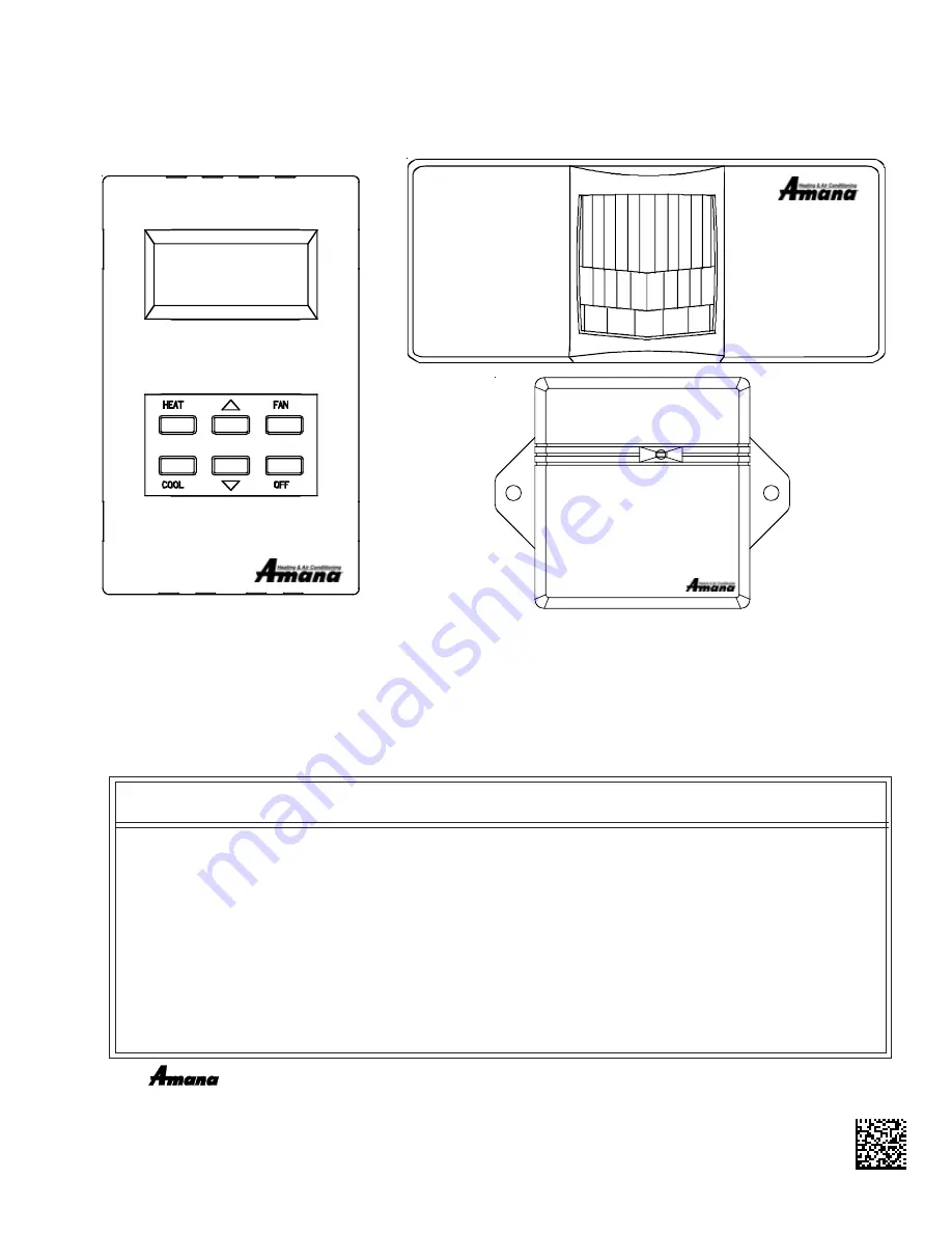
USE ONLY ONE DD01* PASSIVE INFRARED MOTION SENSOR (PIR) DOOR SWITCH

COMBINATION DEVICE AND/OR ONE DS01* TO ONE DIGISMART PTAC UNIT.

DS01*

DD01*

DT01*

AIR CONDITIONING SENSOR

ATTENTION INSTALLING PERSONNEL

As a professional installer you have an obligation to know the product better than the customer.

This includes all safety precautions and related items.

Prior to actual installation, thoroughly familiarize yourself with this Instruction Manual.

Pay special attention to all safety warnings. Often during installation or repair

it is possible to place yourself in a position which is more hazardous than when the unit is in operation.

Remember, it is 

your 

responsibility to install the product safely and to know it well enough

to be able to instruct a customer in its safe use.

Safety is a matter of common sense...a matter of thinking before acting.

Most dealers have a list of specific good safety practices...follow them.

The precautions listed in this Installation Manual are intended as supplemental to existing practices.

However, if there is a direct conflict between existing practices and the content of this manual,

the precautions listed here take precedence.

IO-644C~IO-644C~092007~4

Goodman Company, L.P.

5151 San Felipe, Suite 500

  •  

Houston, TX 77056

www.amana-ptac.com

  •  

©

 2005 - 2007 Goodman Company, L.P.

Due to policy of continued product improvement, the right is reserved to change specifications and design without notice.

®

 is a trademark of Maytag Corporation and is used under license to Goodman Company, L.P.  All rights reserved.

Summary of Contents for DD01*

Page 1: ... possible to place yourself in a position which is more hazardous than when the unit is in operation Remember it is your responsibility to install the product safely and to know it well enough to be able to instruct a customer in its safe use Safety is a matter of common sense a matter of thinking before acting Most dealers have a list of specific good safety practices follow them The precautions ...

Page 2: ...e wires when you connect the cable to the PTAC Gently push into place with your thumb nails 8 Restore power to the PTAC unit 9 Reinstall the polymer room cover NOTE The LED must be oriented at the top of the antenna housingforproperunitoperation ThermostatInstallationforDS01 Kit NOTE A DT01 must be installed in the PTAC unit for the DS01 to be operable Skip these steps if not installing 1 Select t...

Page 3: ... bottom center of the motion sensor DD01 when the door is closed Select the correct slot in the magnet holder there are three slots to obtain 1 2 from back of sensor mounting plate to the center of the magnet If you can easily slide a business card between the magnet and the DD01 sensor unit is properly placed vertically Screw in place with the 2 screws provided Open and close the door to make sur...

Page 4: ... and select the slot that places the magnet as close as possible to the depth from the back of the DD01 mounting plate 1 8 max DOOR TRIM MAGNET POSITION A Place magnet in Position A in instances when the door trim extends beyond the door DOOR TRIM MAGNET DOOR 1 8 max POSITION C Place magnet in Position C in instances when the door extends beyond the door trim DOOR TRIM MAGNET 1 8 max POSITION B Pl...

Page 5: ...If does not show on the display in 1 2 seconds then press and release the white button a second time Skip this step if there is no thermostat 3 Press and then immediately release the white tactile button on the back of the DD01 motion sensor or should now be displayed on the PTAC LED display If or does not show on the display in 1 2 seconds then press and release the white button a second time NOT...

Page 6: ...t you can change for each configuration setting Ensure that you are in the proper configuration setting before pressing the or key as you may accidentally change a setting that you did not intent to change The display will alternate between displaying the feature code and the option code 0 factory default setting If in version 2 5 or higher press the HEAT button one time to get into C1 mode and th...

Page 7: ...back temperature press the HEAT key until feature code comes up To scroll to a previously viewed feature codes press the COOL key Once you have scrolled to the feature press either the up or down arrow to scroll to the desired first unoc cupied setback temperature Cooling example 720 guest set point 20 Setback temperature 740 operational set point 5 Press HEAT key to scroll to first unoccupied set...

Page 8: ...omply with FCC RF exposure requirements in section 1 1307 a minimum separation distance of 20cm 8 inches is required between the equipment and all persons 9 Press HEAT key to scroll to third unoccupied setback time Press either the up or down arrow to the desired third unoccupied setback time 10 To exit configuration mode Press the OFF key NOTE Configuration feature mode will also automatically ex...

Reviews: