background image

3A1183C

EN

Operation/Repair/Parts

Airless Paint Sprayer

For application of architectural paints and coatings. For professional use only.

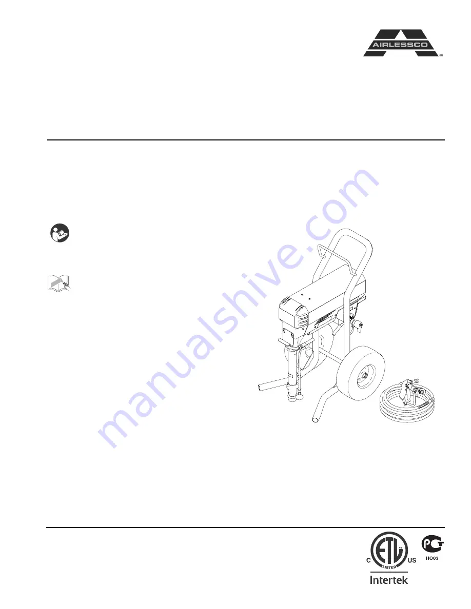
Airlessco - TS1500 (24F573) Series B

3300 psi (22.8 MPa, 228 bar) Maximum Working Pressure

Related Manuals

Important Safety Instructions

Read all warnings and instructions in this 
manual. Save these instructions.

Gun Manual 3A0413

ti17342a

Summary of Contents for 24F573 B Series

Page 1: ...ctural paints and coatings For professional use only Airlessco TS1500 24F573 Series B 3300 psi 22 8 MPa 228 bar Maximum Working Pressure Related Manuals Important Safety Instructions Read all warnings and instructions in this manual Save these instructions Gun Manual 3A0413 ti17342a ...

Page 2: ...electric shock When repair or replacement of the cord or plug is required do not connect the grounding wire to either flat blade terminal The wire with insulation having an outer surface that is green with or without yellow stripes is the grounding wire Check with a qualified electrician or serviceman when the grounding instructions are not completely understood or when in doubt as to whether the ...

Page 3: ...ing halogenated hydrocarbons Keep spray area well ventilated Keep a good supply of fresh air moving through the area Keep pump assembly in a well ventilated area Do not spray pump assembly Do not smoke in the spray area Do not operate light switches engines or similar spark producing products in the spray area Keep area clean and free of paint or solvent containers rags and other flammable materia...

Page 4: ...t Know how to stop the unit and bleed pressure quickly Be thoroughly familiar with the controls EQUIPMENT MISUSE HAZARD Misuse can cause death or serious injury Always wear appropriate gloves eye protection and a respirator or mask when painting Do not operate or spray near children Keep children away from equipment at all times Do not overreach or stand on an unstable support Keep effective footi...

Page 5: ... or on skin inhaled or swallowed Read MSDSs to know the specific hazards of the fluids you are using Store hazardous fluid in approved containers and dispose of it according to applicable guidelines PERSONAL PROTECTIVE EQUIPMENT You must wear appropriate protective equipment when operating servicing or when in the operating area of the equipment to help protect you from serious injury including ey...

Page 6: ...increase pressure and counterclockwise to decrease pressure C Prime Pressure Relief Valve Primes pump and relieves pressure from gun hose and tip D Prime Pressure Relief Valve Closed Position Pressurizes system when closed E Prime Pressure Relief Valve Open Position Relieves pressure from gun hose and tip and primes the unit when in the open position Refer to Pressure Relief Procedure page 13 F He...

Page 7: ...pail and gun Flush before changing colors before fluid can dry in the equipment at the end of the day before storing and before repairing equipment Flushing 1 Make sure the gun trigger lock in engaged and there is no spray tip in the gun Refer to the separate To reduce the risk of static sparking fire or explosion which can result in serious bodily injury and property damage always ground the spra...

Page 8: ...pail forcing the solvent from the pump and hose When paint starts coming from gun turn pressure control knob to minimum pressure place prime pressure relief valve in prime open position and engage the gun trigger lock 11 If you are going to store the sprayer remove the suction tube or pump from the solvent pail force the solvent from the pump and hose Engage the gun trigger lock See Storage 9 12 W...

Page 9: ...ff sprayer Relieve Pressure page 13 and make sure prime pressure relief valve is left open Start Up After Storage Before using water base paint flush sprayer with soapy water and then a clean water flush When using oil base paint flush out the mineral spirits with the material to be sprayed NOTE Always store unit indoors Optional Air Atomizer For best performance use at least a minimum of 1 gallon...

Page 10: ...to a length of 5 8 Brush wear is greatly influenced by individual application and it is recommended that brush wear be checked at early intervals of operation in order to determine future required inspection To change the brushes 1 Unplug the machine 2 Remove the cover over the motor 3 Open the two covers at the rear of the motor 4 Loosen the screw under the brush 5 Pull out the wire 6 Push the br...

Page 11: ...rd with thumb 20 ft lbs NOTE When placing belt on pulleys and inserting the tensioner against belt ensure cogs on belt are engaged into cogs on pulleys before tightening belts Rotating upper pulley while holding the tensioner against the belt will allow proper engagement of cogs prior to tightening Servicing the Fluid Pump NOTE Before disassembling the sprayer refer to Trou bleshooting to try and ...

Page 12: ... locknuts evenly to 30 ft lb NOTE After all the rod locknuts are tight the alignment of both rods should allow easy assembly and disassem bly of the coupling If any binding loosen and retighten all the rod locknuts to improve the alignment Misalign ment causes premature wear of seal and packings 7 Tighten packing nut clockwise until resistance against the packings can be felt Turn it one full turn...

Page 13: ... and the outside of the piston rod which must not be worn or scratched Replace worn or damage parts 2 Remove and clean the sleeve when you are repack ing the pump Repair When Pump is Off the Sprayer Disassembling the pump 1 Remove packing nut 202 and throat adjustment spacer 228 The system pressure must be manually relieved to pre vent the system from starting or spraying accidentally To reduce th...

Page 14: ... Sleeve may come out of cylinder with piston rod 5 Remove piston rod from sleeve or remove sleeve from cylinder 6 Unscrew piston valve from piston rod Clean and inspect parts The piston has a special thread lock ing sealing patch Do not remove the patch The patch allows for disassembly assembly procedures before it is necessary to apply Loctite to the threads 7 Remove packings and glands from pist...

Page 15: ...asher 229 on piston valve 210 The special sealing patch on piston valve threads is good for four repackings Use Loctite on piston valve threads after four repackings 2 Install ball 206 in piston rod If Loctite is applied to piston valve threads ensure that none gets on ball 3 Tighten piston valve to piston rod as specified 4 Soak all leather packings in SAE 30W oil for 1 hour minimum prior to asse...

Page 16: ...7 Slide piston assembly into bottom of sleeve 8 Grease top inch or two of piston rod that will go through the cylinder throat packings 9 Grease O rings 221 and place on sleeve Slide sleeve piston rod assembly into bottom of cylinder Replace O ring 207 if desired NOTE O ring 207 is not required for safe pump opera tion 203 224 223 204 7573f 7581a 201 202 228 7578c NOTICE Do not slide piston assembl...

Page 17: ...er cord 2 Remove screws and lower the pressure control assembly 3 Disconnect all leads from pressure control assem bly 4 Reassemble in reverse order Sensor 1 Remove the screws and lower the pressure control assembly 2 Disconnect sensor lead from the board 3 Unscrew sensor from pressure control assembly using a 3 4 wrench 4 Reassemble in reverse order Use PTFE tape on the sensor threads prior to re...

Page 18: ... power switch is OFF and the machine is unplugged 2 Detach the pressure control assembly from the frame by unscrewing the two screws 3 Disconnect the LCD lead from the pressure control assembly 4 Separate the LCD assembly from the frame by undoing the eight screws 5 Disassemble LCD from the control by removing the retaining screws 6 Remove and replace LCD Display 7 Reassemble in reverse order NOTE...

Page 19: ...rn Service outlet valve Prime pressure relief valve bypassing Clean or replace Prime Pressure Relief Valve Packings and or piston worn Tighten packing nut repack unit Unit does not maintain good spraying pressure Blown spray tip Replace spray tip Packings and or pistons worn Repack unit Upper seat worn Replace upper seat Unit does not run See Machine Does Not Start Machine does not start Control S...

Page 20: ...nt sensor available use a multi meter to test the resistance across the red and black wires of the sensor be sure to test the plug You should read 1 5 3 5k ohms A faulty sensor usually reads no conti nuity open If the sensor passes all the tests see Pres sure Control Knob Potentiometer Pressure Control Knob Poten tiometer Plug another potentiometer POT into the control board If the machine starts ...

Page 21: ...hree times repeatedly Sprayer shuts down and LED continues to blink four times repeatedly Pressure transducer is faulty or missing Check transducer connection Open prime pressure relief valve Substitute new transducer for transducer in sprayer If sprayer runs replace transducer Four times repeatedly Sprayer shuts down and LED continues to blink four times repeatedly Line voltage is too high Check ...

Page 22: ...ssure transducer faulty bad connection or broken wire Check transducer connection Open prime pressure relief valve Substitute new transducer for transducer in sprayer If sprayer runs replace transducer Sprayer stops Power is applied Line voltage too high Check for voltage supply problem Sprayer does not start or stops Power is applied Motor fault Check for locked rotor shorted wiring or disconnect...

Page 23: ...size Coating fails to close and smooth over Material too viscous Thin cautiously Spray pattern irregular deflected Orifice clogged Clean carefully Tip damaged Replace with new tip Craters or pock marks bub bles on work Solvent balance Use 1 to 3 short solvents remainder long solvents this is most likely to happen with material of low viscosity lacquers etc Clogged screens Extraneous material in pa...

Page 24: ...s in paint Thoroughly strain the paint before use Gun filter missing Do not operate without inlet strainer Coarse filter mesh Do not operate without inlet strainer Problem Cause Solution Test the Pattern Good Full Spotty Pattern Increase Pressure ti15991a ...

Page 25: ... 6 305140 BRACKET FILTER 1 7 867534 SCREW 5 16 18 x 1 00 PH HD not shown 2 8 331103 WASHER 562 250 060 ST 2 9 121112 SCREW CAP SOCKET HEAD 2 10 867400 HOSE PAINT 3 8 x21 LG 1 11 557391 PLUG 1 4 NPT 1 12 866052 CAP PLUG SET 25 1 ti16036a 1 12 5 6 9 8 4 3 10 11 1 2 3 4 5 6 ti16037a Ref Part Description Qty 1 867145 BASE 1 2 301356 SPRING 1 3 867377 O RING 1 4 867214 FILTER 60 MESH 1 5 867647 SUPPORT...

Page 26: ...1 22 DISPLAY LCD 1 23 867798 DISPLAY WINDOW 1 24 867816 SCREW MACH PHILLIPS FLAT HD 2 25 117281 SPACER 6 X 312 2 27 867817 NUT HEX 2 28 867803 LABEL CONTROLS SL 1 31 301083 SWITCH TOGGLE 1 32 301150 BOOT RUBBER BLACK 1 34 256219 POTENTIOMETR ASSEMBLY 1 38 866049 CABLE ASSY 9 LG 1 59 110637 SCREW MACH PANHEAD 13 62 867252 GROMMET 1 82 HSE3850 HOSE 3 8 x 50 255439 HOSE CPLD 1 4 x 3 96 24F690 GUN MAS...

Page 27: ...rts 3A1183C 27 Motor and Drive 84 61 57 68 65 67 76 78 77 77 55 83 70 71 52 79 63 69 72 74 45 80 49 49 51 50 50 75 66 65 64 46 44 47 43 41 48 73 85 81 60 58 60 59 115 12 13 53 54 94 93 10 42 6 5 ti17477a ...

Page 28: ...USA ASSY 1 57 301106 MOTOR 1 58 301321 COVER 1 59 110637 SCREW MACH PANHEAD 13 60 301135 GROMMET 6 61 865180 TRIM EDGE RUBBER 2 63 301193 BRACKET TENSIONER 1 64 100057 SCREW CAP HEX HD 2 65 100214 WASHER LOCK 6 66 867704 WASHER PLAIN 5 16 NOMINAL 2 67 111303 NUT HEX 4 68 140029 WASHER PLAIN 4 69 100307 NUT HEX 3 70 301044 SCREW MODIFIED 3 71 301099 RETAINER 5 8 18 3 72 866455 PULLEY 69 TEETH MACHI...

Page 29: ...125 PACKING VEE 4 11 15E329 PACKING VEE 3 12 183178 PACKING GLAND MALE 1 13 BALL BEARING 1 14 107098 PACKING O RING 2 15 PACKING O RING 1 16 196866 SEAT CARBIDE 1 17 108526 PACKING O RING 1 18 196967 GUIDE BALL 1 19 102972 BALL METALLIC 1 20 15C989 GLAND PACKING 1 21 193124 PACKING VEE 4 22 183175 PACKING VEE LEATHER 3 23 15C990 GLAND PACKING 1 24 183171 PLUG 1 25 C20987 PACKING O RING 1 28 WIPER ...

Page 30: ...DAPTER VALVE 1 3 15G563 HANDLE VALVE 1 4 867759 CONNECTOR MALE 3 8 TUBE x 1 8 PIPE 1 8 116424 NUT CAP 1 2 3 4 8 ti16004a Ref Part Description Qty Ref Part Description Qty 1 866203 SWIVEL FITTING ASSY 1 4 301545 55 GAL SUCTION TUBE 1 2 866388 1 ID SUCTION HOSE 1 5 867446 CLAMP 1 3 187190 FILTER BASKET 1 ti16039a 2 1 4 3 5 ...

Page 31: ... HOSE DRAIN 1 84 867759 CONNECTOR MALE 3 8 TUBE X 1 8 PIPE 2 86 865013 ADAPTER VALVE 1 87 865719 VALVE DRAIN ASSY 1 88 15G563 HANDLE VALVE 1 89 116424 NUT CAP 1 90 114708 SPRING COMPRESSION 1 91 193709 SEAT VALVE 1 92 193710 SEAL SEAT VALVE 1 120 CONTROL BOARD 120V 1 121 867796 GASKET COVER SL 1 122 HEAT SINK MACHINED SL 1 125 SPACER CONTROL BOARD 6 126 SCREW MACH PHILLIPS PAN HD 6 129 100272 WASH...

Page 32: ... from Motor Red White Black Green 2 x White Black Black Black ti12471a 1 4 6 7 8 Ref Part Description Qty Ref Part Description Qty 1 331168 ELECTRICAL CORD110V 1 7 24B599 SENSOR 1 4 301083 TOGGLE SWITCH 1 8 256219 POTENTIOMETER 1 6 PRESSURE CONTROL ASSY 110V 1 ...

Page 33: ...required 3000 w minimum Maximum working pressure 3000 psi 20 7 MPa 207 bar Maximum delivery gpm lpm 1 1 GPM Maximum tip size 033 Fluid outlet npsm 3 8 Weight 145 lb 65 7 kg Wetted parts zinc and nickel plated carbon steel nylon stain less steel PTFE acetal leather UHMWPE aluminum tungsten carbide ...

Page 34: ... any defective parts The equipment will be returned to the original purchaser transportation prepaid If inspection of the equipment does not disclose any defect in material or workmanship repairs will be made at a reasonable charge which charges may include the costs of parts labor and transportation THIS WARRANTY IS EXCLUSIVE AND IS IN LIEU OF ANY OTHER WARRANTIES EXPRESS OR IMPLIED INCLUDING BUT...

Reviews: