background image

I N S T A L L A T I O N  I N S T R U C T I O N S 
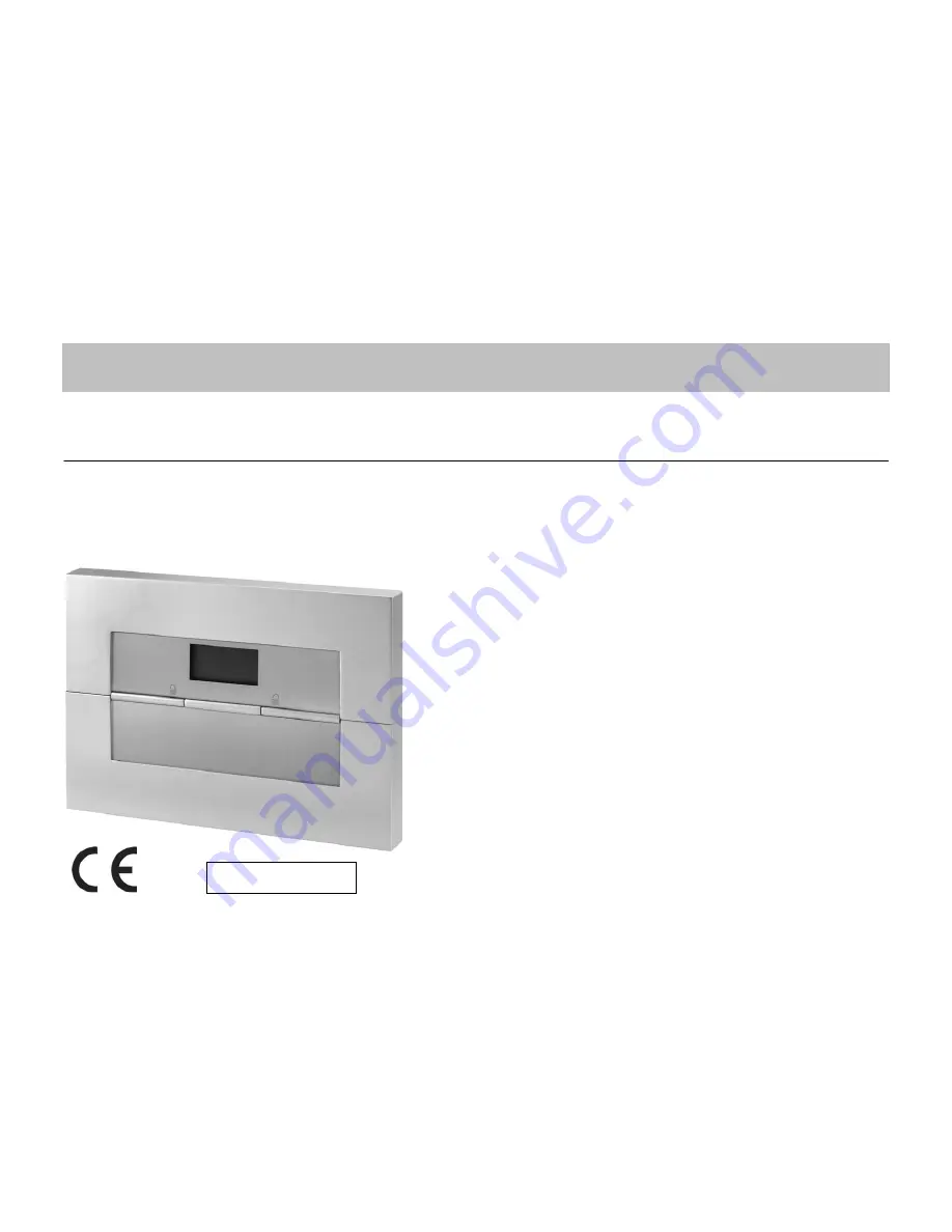
 

Radio alarm panel 

SECVEST 868 


INSTALLATION INSTRUCTIONS 


Perfect security for home and office


These installation instructions are an important product 
accessory. They contain important installation and operation 
information. Bear this in mind if you pass the product on to 
others. Store these installation instructions in a safe place for 
future reference. 
For a list of contents with page numbers, see page 3.


Inv.: 11772609 

Summary of Contents for SECVEST 868

Page 1: ...nd office These installation instructions are an important product accessory They contain important installation and operation information Bear this in mind if you pass the product on to others Store...

Page 2: ...manual The contents of this manual are subject to change without notice 1 Usage in accordance with regulations This radio alarm panel uses detectors and transmitters to secure your property You can us...

Page 3: ...ecting partitions 22 10 3 4 Selecting zone attribute 22 10 3 5 Adding deleting a detector 23 10 4 Configuring outputs 26 10 4 1 Editing outputs 26 10 4 2 Defining output name 27 10 4 3 Selecting outpu...

Page 4: ...ial Care 72 10 10 3 Configuring speech dialler 77 10 10 4 SMS 81 10 10 5 Line Fail Reporting 85 10 11 Configuring social care 86 10 11 1 Start End Monitoring at 86 10 11 2 Monitoring Interval 87 10 11...

Page 5: ...DC power by means of the internal transformer The transformer is connected to the 230V AC building mains by means of a separate electrically protected line Connection work to the building mains is su...

Page 6: ...on DVD Downloader CD You also need Alarm detector Signal transmitter Optionally available Info module Wireless control Panel Secvest Key Remote Control WAM Wireless Accessory Module ISDN module GSM mo...

Page 7: ...ned radio components according to the zone programming and can also analyse radio communication for attempts to tamper with it Properties of alarm station 32 freely programmable radio zones all of whi...

Page 8: ...rticular note of the cable connections 6 2 Connections in the upper part The following figure shows the connections in the upper part Number Description 1 Internal siren 2 Battery case 3 Internal loud...

Page 9: ...for wired zones and outputs 6 4 Blanking off non used cable inputs Use the plastic blanks supplied to blank off the cable inputs that are not used See next figure for fitting 6 5 Installing the base...

Page 10: ...a fuse of the same type and never with a higher rated fuse 6 7 Connecting wired detectors optional Connect wired components as shown in the diagram Note that sensors can be connected in only one way...

Page 11: ...aker microphone to the radio alarm panel as shown in the diagram For this order the FU extension set 6 10 Adjusting the loudspeaker volume You can adjust the volume of the internal external loudspeake...

Page 12: ...es short circuit the kickstart jumper on the upper side of the alarm panel to put the radio alarm panel into operation 6 14 Final steps You have now made all connections and the radio alarm panel is r...

Page 13: ...contact ENTRY ROUTE This zone triggers no alarm if an entry exit zone has previously activated the entry delay time An immediate alarm is triggered if no entry delay is first activated You can use thi...

Page 14: ...larm panel can return to active state Notes 1 These two zone types are intended for use on zones that connect to an access control keypad electronic key or other type of hardwired device used to set o...

Page 15: ...ated individually Each detector can be assigned to one or more partitions The detector is not monitored until all partitions to which the detector is assigned have been activated exception detectors t...

Page 16: ...isplay Button for activating radio alarm station Keypad for programming and operating the station Keypad cover Integrated siren and loudspeaker Button for deactivating radio alarm station Control butt...

Page 17: ...and right refer to the LCD display and have various functions 10 Settings in installer mode 10 1 First steps in installer mode In user mode do the following Enter a valid installer code 7 8 9 0 Facto...

Page 18: ...es Install external sirens WAM Wireless Accessory Module info module remote radio alarm panel Partitions Assign partitions to zone configure partitions System Options Perform user functions select lan...

Page 19: ...To cancel input press the control button under the word Back After confirming Edit Zones with the Select button you receive the following graphic display This shows you a summary of the configuration...

Page 20: ...he word Select To cancel input press the control button under the word Back NOTE Wireless remote controls and pendants are not learned into the panel in this menu but are added to the user Please lear...

Page 21: ...to select Type Confirm by pressing the control button under the word Select To cancel input press the control button under the word Back If you confirm Type with the Select button you see the followin...

Page 22: ...w you to assign zones of the following types to more than one partition 24 Hour Fire Panic Alarm and Technical 10 3 4 Selecting zone attribute After entering the partition use the control buttons to s...

Page 23: ...dding deleting a detector After programming zone attributes for all zones exit the menu items until you see the following graphic display Using the control buttons select Add del detectors Confirm you...

Page 24: ...uto learn you see the following graphic display Now trigger the tamper contact of the detector The detector sends the learn message to the radio alarm station If you do not want to train any further d...

Page 25: ...e the display is meaningless 10 3 5 2 Delete All If you confirm Delete All you see the following graphic display Confirm that you want to delete all zones by pressing the control button under the word...

Page 26: ...input press the control button under the word Back 10 4 1 Editing outputs If you confirm Edit with the Edit button you see the following graphic display For the meaning of the menu items see Table 6...

Page 27: ...et and unset the panel at a certain time automatically Please see the note on the next page output type user defined After entering the output name use the control buttons to select Type Confirm by pr...

Page 28: ...dio alarm station Siren P1 P4 This output is activated on local alarms in the selected partition for the defined siren duration Strobe P1 P4 This output is activated for a local alarm in the selected...

Page 29: ...lso be controlled via the remote control Make sure that you program this function in the users menu system setup remote controls see user manual Proceed as follows to add a radio output not for Wirele...

Page 30: ...he receiver beeped twice the learn message was correctly received End the teach process by pressing the control button under the word Yes To cancel input press the control button under the word No The...

Page 31: ...0 5 1 External siren Optional radio external siren not a combination of external siren and Wireless Accessory Module If you confirm External Siren Menu with Select you see the following graphic displa...

Page 32: ...ly describes training sirens that need no Wireless Accessory Module to control them 10 5 2 Info module 10 5 2 1 Teach Info module If you confirm Info Module with Select you see the following graphic d...

Page 33: ...dule menu provides the Updates option for this purpose 1 Select Other Devices Info Module Updates The display shows the options Disabled and Enabled 2 Select the option you require When you select Ena...

Page 34: ...e with the zone attribute force omit set the info module LED for open zone is lid This indicates that the panel cannot be set or only with zones omitted 10 5 3 Wireless Accessory Module WAM If you con...

Page 35: ...module for connecting wired detectors water detectors or a block lock key switch Sounder Module For connecting a wired external radio siren or compact alarm device IMPORTANT See the WAM product instr...

Page 36: ...connect the compact alarm device to the WAM see the WAM operating instructions 10 5 4 Arming station If you confirm Arming station with Select you see the following graphic display Press the control b...

Page 37: ...n Full Set After you enter the user code and press this button the alarm panel is fully activated Part Set After you enter the user code and press this button a partition of the alarm panel is armed U...

Page 38: ...to define the exit mode of the partition For exit mode attributes see Table 9 Ext Time Exit delay time for this partition Ent Time Entry delay time for this partition Alarm Rsp Response to alarm in t...

Page 39: ...vated following expiry of the defined exit time Final Door Set The partition is activated when you close a zone with the final door property Instant Set The partition is activated immediately This exi...

Page 40: ...efine the entry delay in the same way as the exit delay Configure the entry delay for each exit mode 10 6 4 Activating alarm response of partition After entering the delay times use the control button...

Page 41: ...this zone In this case change the zone attribute to Normal Alarm so that an intruder who enters the house via the entrance door triggers an instant alarm Confirm your selection by pressing the control...

Page 42: ...taller code For entering a new user code Entry timer unset To unset the panel partition with a wireless remote control during the entry delay If this function is activated you can only unset the panel...

Page 43: ...message Reset after alarm Enables the user to reset the radio alarm panel following an alarm If you wish to allow users to reset the system after an alarm then select Y If you wish to make sure that...

Page 44: ...perator can still use the speech dialler commands but cannot use the remote control commands Call in control If you set this option to Y then the remote operator can call the radio alarm panel After s...

Page 45: ...he setting relates to the language selected Factory defaults Confirm this function to reset all settings to the factory defaults for the selected country However select Factory Defaults does not erase...

Page 46: ...unning To select a function press the control button under the word Select To cancel input press the control button under the word Back 10 7 7 PA Response Use the control buttons to select PA Response...

Page 47: ...ot detectors that are still sending alarm signals If the system has rearmed then when a user enters the system through the entry route the radio alarm panel will give an audible internal alarm in plac...

Page 48: ...lay and confirm by pressing the control button under the word Select To cancel input press the control button under the word Back If you confirm Stray on Entry Route Delay with the Select button you s...

Page 49: ...hours the radio alarm panel raises an alarm Function Meaning for activated system Meaning for deactivated system Disabled No response No response Fault Fault is reported by telephone Fault is reporte...

Page 50: ...by pressing the control button under the word Select To cancel input press the control button under the word Back If you confirm Batt Load Test with the Select button you see the following graphic dis...

Page 51: ...s the control button under the word Back If you confirm Force Set with the Select button you see the following graphic display Use the control buttons to select the option On All zones with the zone a...

Page 52: ...s comprises four groups of digits Each group is three digits long and is separated from the next group by a dot for example 192 168 000 001 Press to key in the dot Note If you leave this field blank t...

Page 53: ...n via GPRS you can see what IP address the radio alarm panel has by selecting the System Config About Comms IP Address option from the Operating menu GPRS APN Access Point Name Key in the text of the...

Page 54: ...type of connection setup is to be made by telephone Phone Book Enter two numbers here One is used for secure callback IP Network If you have fitted an Ethernet GPRS module to the radio alarm panel the...

Page 55: ...does not work with this option Note This option will not work if System Options Remote Access Call in Control is set to Y Note The radio alarm panel will leave the Connection Type menu if Downloader d...

Page 56: ...ves within 10 to 90 seconds the panel accepts the call immediately This skips the Rings to Answer function Note When using Answer on One Ring set the number of rings in Rings to Answer to a higher num...

Page 57: ...t until the first attended upload has been performed This first upload can be carried out either from User Menu or from Installer Menu Note The Downloader operator can choose to use Secure Callback ev...

Page 58: ...alternate IP address 10 9 8 Secure Callback Use the control buttons to select Secure Callback Confirm your selection by pressing the control button under the word Select To cancel input press the con...

Page 59: ...uld set a lower baud rate Set the value to 300 To confirm this setting press the control button under the word Select To cancel input press the control button under the word Back 10 10 Configuring com...

Page 60: ...menu 10 10 1 Configuring alarms Use the control buttons to select Alarms Confirm your selection by pressing the control button under the word Select To cancel input press the control button under the...

Page 61: ...urg Settings for transmitting a tamper alarm as intrusion alarm Table 19 Menu items in the ALARMS menu 10 10 1 1 Call Mode Use the control buttons to select Call Mode Confirm your selection by pressin...

Page 62: ...control button under the word Back 10 10 1 3 Phone Book Alarms Use the control buttons to select Phone Book Confirm your selection by pressing the control button under the word Select To cancel input...

Page 63: ...y in a string of up to 32 characters This string must be unique for each radio alarm panel communicating to a receiver Polling Eng IP Address Key in the IP address of the IRIS polling engine The IP ad...

Page 64: ...ID in SMS then you must store the phone number of the ARC in Reporting Alarms Phone Book 10 10 1 7 Fast Format Use the control buttons to select Fast Format Confirm your selection by pressing the cont...

Page 65: ...channels are preset as follows Channel Setting 1 Fire 2 Panic 3 Intrusion 4 Enabled disabled 5 Not used 6 Not used 7 Not used 8 Technical alarm 10 10 1 8 Fast Format Restore Use the control buttons t...

Page 66: ...asic SIA Code Summary SIA Code Intermediate SIA Code Full SIA Code Code without Zn No without User Code without Zn No without User Code Zn No User Code Zn No User KEYPAD MEDICAL MA MA MA MA FIRE FA FA...

Page 67: ...RT LB LB LB PROG MODE END LS LS LS USER CODE CHANGED JV USER CODE DELETED JX PASSWORD DEFAULTS LOADED RH RH EXIT TIMEOUT EA EA EA EA NOTE In Germany and Austria we recommend the following digital prot...

Page 68: ...ontrol button under the word Back 10 10 1 11 Contact ID Use the control buttons to select Contact ID Confirm your selection by pressing the control button under the word Select To cancel input press t...

Page 69: ...0 150 KEYBOX CLOSED 150 150 TECHNICAL ALARM 150 TECHNICAL ALARM RESTORE 150 150 AC LOST 301 301 AC RESTORE 301 RESET 305 305 LOW BATT 311 311 LOW BATT RESTORE 311 BATT MISSING 311 311 BATT MISSING RES...

Page 70: ...rd Back If you confirm Dynamic Test Call with the Select button you see the following graphic display Use the control buttons to select whether the panel is to make a test call every 24 hours If the f...

Page 71: ...e you specified This is to make sure that the ARC is not overwhelmed with a flood of test calls from systems that have all been given the same time Select Reporting Alarms Static Test Call Disabled to...

Page 72: ...transmit an alarm via digital protocol If you want to send a speech message please select the next option The radio alarm panel sends a social care alarm message for the following types of alarm Emerg...

Page 73: ...lection by pressing the control button under the word Select To cancel input press the control button under the word Back If you confirm Call Mode with the Select button you see the following graphic...

Page 74: ...the control button under the word Back 10 10 2 3 Phone Book Use the control buttons to select Phone Book Confirm your selection by pressing the control button under the word Select To cancel input pre...

Page 75: ...acters then the radio alarm panel pads the number of digits out to six by adding leading zeros When using Tunstall report type the radio alarm panel adds leading zeros to make shorter account codes ei...

Page 76: ...e caller Note that you will have to use the Speech Dialler menu to record the Home Message 3 The radio alarm panel sends an SMS message see SMS Reporting 10 10 2 6 Call Acknowledge Use the control but...

Page 77: ...w If a Social Emergency or Social Inactivity trigger starts a speech call then the radio alarm panel also opens a speech path the to the called number The person receiving the speech messages can cont...

Page 78: ...r selection by pressing the control button under the word Select To cancel input press the control button under the word Back If you confirm Messages with the Select button you see the following graph...

Page 79: ...l input press the control button under the word Back After selecting a message select the corresponding report trigger Then define the report trigger that causes the alarm to be transmitted with this...

Page 80: ...rs you selected 10 10 3 7 Call Acknowledge Use the control buttons to select Call Acknowledge Confirm your selection by pressing the control button under the word Select To cancel input press the cont...

Page 81: ...10 4 SMS In addition to alarm transmission by digital report or voice text the panel can also send an event by SMS The radio alarm panel can send alarm reports by SMS message to any of four telephone...

Page 82: ...ra information under this menu 10 10 4 1 Call Mode This option enables or disables SMS reporting To employ SMS reporting set the call mode to Enabled 10 10 4 2 Primary Telecoms Press the control butto...

Page 83: ...SMS message select Reporting SMS Phone Book Highlight and select the telephone number you wish to program and key in the correct digits When you have completed keying in the telephone number press DO...

Page 84: ...tes see the table below Confirm your selection by pressing the control button under the word Select To cancel input press the control button under the word Back Function Meaning Protocol Select the pr...

Page 85: ...splay Use the control buttons to select whether the telephone line is to be monitored and how a fault is to be reported to the user Confirm your selection by pressing the control button under the word...

Page 86: ...e voice connection 10 11 1 Start End Monitoring at Use the control buttons to select Start Monitoring at Confirm your selection by pressing the control button under the word Select To cancel input pre...

Page 87: ...e monitoring period defined by the monitoring start and end times To confirm the interval entered select OK by pressing the control button under the word OK 10 11 3 Set Volume Voice Connection After t...

Page 88: ...the local siren in the alarm station Loudspeaker Tests the function of the local loudspeaker in the alarm station Keypad Tests the keypad input function Walk Test Go through each programmed detector...

Page 89: ...ON appears You see the following graphic display To end the test select On Off again 10 12 2 Testing the loudspeaker Use the control buttons to select Loudspeaker Confirm your selection by pressing t...

Page 90: ...Use the control buttons to select Walk Test Confirm your selection by pressing the control button under the word Select To cancel input press the control button under the word Back If you confirm Wal...

Page 91: ...should be higher than 3 10 12 9 Outputs The test of the outputs is used for displaying the signal strength The signal strength should be higher than 3 10 12 10 Telecommands Press the buttons of the t...

Page 92: ...the ninth menu item You see the following graphic display Select this menu item by pressing the control button under the word Select You see the following graphic display To cancel the display press...

Page 93: ...ion and disconnect the connecting cable between the base plate and the upper section Turn the upper section round and remove the four housing screws 1 on the bottom of the upper section Make sure you...

Page 94: ...dule You can use any SIM card whose PIN code can be disabled or where the SIM PIN has been changed to 0000 in advance If you have not done so already first place the SIM card in a mobile phone and dis...

Page 95: ...ule You can use any SIM card whose PIN code can be disabled or where the SIM PIN has been changed to 0000 in advance If you have not done so already first place the SIM card in a mobile phone and disa...

Page 96: ...s connected you will receive an error message such as Telephone error or Telephone transmission error In this case check the setting of the primary transmission path and change it accordingly 11 7 Aut...

Page 97: ...the software CD supplied You can also obtain the current version of this program in the download area of the Security Center homepage After installing and starting the downloader program you are prom...

Page 98: ...ity EN50130 5 Class 1 93 relative humidity Inputs outputs Wired outputs 2 x 24V DC 1A or 120V AC 0 5A Wired inputs 2 x DEOL Radio outputs 32 Radio inputs 32 Security Security level EN50131 1 Level 2 E...

Page 99: ...ions 285mm x 206mm x 45mm HxWxD Weight 1 060g Internal time 10min per year Behaviour of the panel during mains failure If the panel is unset it will display a message after several minutes In addition...

Page 100: ...tion of the telecommands PAs and detectors that it has learned MAC Media Access Control Ethernet ID NC normally closed NO normally open NTBA Network Termination for ISDN Basic rate Access PABX private...

Page 101: ...rtitions Installer Mode 1 System Options Installer Mode 2 IP Network Installer Mode 2 Downloading Installer Mode 2 Reporting Installer Mode Reporting Social Care Installer Mode 2 Testing Installer Mod...

Page 102: ...Siren Add Del Ext Siren Ext Siren 1 Ext Siren 2 Edit Ext Siren Ext Siren 1 Part1 4 Ext Siren 2 Part1 4 10 5 1 Info Module Teach Info Module 10 5 2 1 Updates Disabled Enabled 10 5 2 2 Rdy to Set LED D...

Page 103: ...on IP Address IP Port Number IP Subnet Mask Gateway IP Address with GPRS plug on IP Address IP Port Number GPRS APN GPRS Username GPRS Password 10 8 Downloading Account name 10 9 1 Connection Type Re...

Page 104: ...ed Single Alternate 10 10 2 1 Primary telecoms PSTN Plug On 10 10 2 2 Phone Book Tel No name Tel No name 10 10 2 3 Account Numbers Account No 1 4 10 10 2 4 Report Type Scancom Scanfast Tunstall 10 10...

Page 105: ...Terminal Equipment and the mutual recognition of their conformity and Annex III Conformity Assessment procedure referred to in article 10 4 Weiterhin erkl ren wir dass Teile aus folgenden Normen und...

Reviews: