ABB HCB, Instruction Leaflet
The ABB HCB Instruction Leaflet is a comprehensive manual for easy installation and operation of the ABB HCB product. Download this user-friendly manual for free at manualshive.com, and get all the important information you need to maximize the benefits of your ABB HCB product.
Share
Download


Reviews:
No comments
Related manuals for HCB

ZB65 Series
Brand: Eaton Pages: 92

773 632
Brand: Pilz Pages: 20

EU 300
Brand: hager Pages: 2

EU400 NA-protection
Brand: hager Pages: 44

NR2 Series
Brand: CHINT Pages: 16

EB3N
Brand: IDEC Pages: 4

FB800E
Brand: CTI Pages: 30

ESM-BA3 Series
Brand: EUCHNER Pages: 3

ESM-2H2 Series
Brand: EUCHNER Pages: 3

NPU
Brand: ComAp Pages: 19
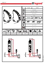
CX3
Brand: LEGRAND Pages: 2
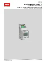
IME Delta D2-B
Brand: LEGRAND Pages: 31

COKP Series
Brand: macromatic Pages: 2

HR1S-ATE
Brand: IDEC Pages: 3

PLL/D-100/120
Brand: TE Connectivity Pages: 4

easy800
Brand: Eaton Pages: 394

CWMC25
Brand: WEG Pages: 2

SIRIUS 3UG4822
Brand: Siemens Pages: 7


