Ref: PLL/D APR11-REV1
Installation and Operating
Instructions
Page 1 of 2
Synchro-check Monitor PLL/D-100/120, PLL/D-173/240,
PLL/D-380/480, PLL/D-277/500 DIN-rail mounted
Introduction
This unit compares the voltage, frequency and phase angle of two
supplies and operates a relay according to the synchronicity of the
supplies. If the two supplies cease to match, the relay operates to
provide a control output. The relay output can be used for alarm or
control purposes.
The unit also provides a dead bus function. If the bus supply fails, the
relay operates and the output can be used to switch in an emergency
generator. LEDs indicate power on, relay and dead bus status.
Controls on the front panel set the trip points at which the relays and
LEDs operate:
Degree of synchronicity Ux (%Volts)
Nominal voltage (Un)
Dead bus function on/off
The unit is powered from the generator supply.
These instructions contain important safety information. Please read
them thoroughly before commissioning, operating or maintenance of
the unit.
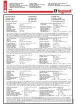
Specification
Parameter
PLL/PLD
100/120 173/240 380/480 277/500
Rated Vg range Un
57-69V
100-
139V
220-
277V
277-
500V
Overload capacity
- continuous
87V
174V
346V
600V
- 10s max.
104V
209V
416V
700V
Minimum supply Vg Uon
35V
60V
132V
166V
Burden on supply (Max)
2 VA /
1.6W
2.7 VA /
1.7W
4 VA /
2.2W
5 VA /
2.8W
Frequency range
45-65 Hz
Deadbus on Udbon
25% Uon
Deadbus off Udboff
50% Uon
Sync Tolerance
10-30% Volts
Relay contacts:
for
general switching
2 x changeover, volt-free
Load capacity - a.c.
250V @ 8A, 2 kVA
Load capacity - d.c.
30V 8A
Insulation
4 kV/1 min
Mech. endurance
30x10
6
operations
Other Data:
Dimensions
90 x 105 x 64 mm
Weight
(100/208/380/277)
291 / 335 / 332 / 335 g
Maximum conductor
size
2 x 1.5 mm
2
or 1 x 2.5 mm
2
Operating temperature
-20 to +55 °C
Storage temperature
-30 to +70 °C
Over-voltage category
III
Pollution degree
2
Environmental
protection
IP40 for front panel
IP20 for terminals.
Standards
EN 60255-6, EN 60255-27, EN 61000-6-2,
EN 61000-6-4
Insulation Class: Ensure any external circuits connected to the
relay are provided with double or reinforced insulation.
Operation
The green
LED lights shows when the power supply is on.
While the two supplies match in voltage, frequency and phase to the
degree set by the %Volts control, the
Sync
LED lights and the relay is
energised.
If one supply varies such that they no longer match to that degree, the
Sync
LED goes off and the relay de-energises.
If the generator voltage falls below the Uon level, the unit ceases to
operate, the relay de-energises and the
Sync
LED goes off.
With Dead Bus On, if the bus voltage falls below the Udbon level, the
relay energises and the
Dead Bus
LED lights. The relay can be used
to turn on an emergency supply in the event of bus supply failure. The
relay will de-energise again and the LED will go off when the bus
voltage rises above the Udboff level.
Note; Red LED indicates fault condition, not relay status
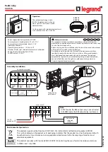
Installation
The unit is intended for mounting on a standard DIN rail. Hook the unit
onto the top of the rail and press the bottom of the unit until it locks in
place. To remove the unit from the rail, lever down the black tabs at
the bottom of the unit to release it from the rail.
The unit is intended for use in a reasonably stable ambient
temperature within the range -20 to +55°C. Do not mount the unit
where there is excessive vibration or in excessive direct sunlight.
The differential trip levels help to prevent relay chatter as the
monitored voltage level varies.
As the relays have changeover contacts, the relay outputs can be
inverted by wiring to the alternative terminals 15-16 or 25-26.