background image

ZyXEL 


OLT-2300 Series Support Notes


All contents copyright 

ٛ

 2006 ZyXEL Communications Corporation.


21


Adding a new device in SNMPc 

This section shows you how to add a new device in SNMPc and access the EMS 
screen.  
 
1. In the edit button bar shown in Figure 4, click the 

Insert Device

 icon to create a 

new device node.    

Figure 4 Adding a new Device


Summary of Contents for OLT-2300 Series

Page 1: ...OLT 2300 Series Chassis based Optical Line Terminal Support Notes Version1 0 Nov 2007 ...

Page 2: ...tication RADIUS Setup 9 RADIUS Server Setup 10 Create User Account 10 Supplicant Setup Windows XP 11 802 1x MD5 challenge setup 11 Port based VLAN Introduction 14 Setting Port based VLAN 14 Centralized Management 18 Introduction to SNMPc and NetAtlas 18 SNMPc Overview 19 EMS Overview 20 FAQ 28 What is the rationale of wavelength division multiplexing WDM 28 Why single mode is necessary for PON net...

Page 3: ...password for console telnet and FTP login 36 How to change the password 36 How to access the Command Line Interface CLI 36 If I have forgotten the password how to reset the password to the default setting 37 How to configure the IP address 37 Is Online Help available on the Web Configurator 37 How to restart device from the Web Configurator 38 How to check the current running firmware version 38 I...

Page 4: ... Management and Maintenance Firmware Upgrade Using the Web Configurator 1 Download and unzipped the correct model firmware to your computer 2 Click Management Maintenance in the navigator panel to display the following screen 3 Click the Click Here link for Firmware Upgrade to display the following screen ...

Page 5: ...ansfer is complete and the firmware upgrade process is done Using FTP 1 Download and unzipped the correct model firmware to your computer 2 Launch the FTP client on your computer to log into OLT From the command prompt type ftp OLT IP 3 Press ENTER when prompted for a user name 4 Enter the administrator login password to access the OLT and display FTP prompt 5 Enter bin to set the transfer mode to...

Page 6: ...ate the firmware file 4 Click Restore to start restoring configuration Using the Console Port 1 Connect to the console port and launch Terminal Emulation software 2 Restart the OLT to enter the debug mode via the terminal 3 Enter ATLC 4 Use X modem protocol to transfer Send File the configuration file with a rom file extension 5 Enter ATGO to restart the OLT after file transfer and the configurati...

Page 7: ...word to access the OLT and display FTP prompt 5 Enter bin to set the transfer mode to binary 6 Use put to transfer the configuration file from the computer to the OLT for example put comfig rom rom 0 transfers the configuration file on your computer config rom to the OLT and renames it to rom 0 7 Enter bye to log out from the OLT Backing Up a Configuration File Using the Web Configurator 1 Click M...

Page 8: ...d the configuration backup processes are complete Using FTP 1 Download and unzipped the correct model firmware to your computer 2 Launch the FTP client on your PC to log into the OLT From the command prompt type ftp OLT IP 3 Press ENTER when prompted for a user name 4 Enter the administrator login password to access the OLT and display FTP prompt 5 Enter bin to set the transfer mode to binary 6 Us...

Page 9: ...s prompt 4 Click OK 5 Click OK again to start the configuration reset process After it is complete the device automatically restarts 6 Please note that the IP address of the OLT is now 192 168 0 1 Using the Console Port 1 Connect to the console port and open the Terminal Emulation Software 2 Enter the administrator login password to log into the CLI Enter erase run to load the factory default conf...

Page 10: ...e configuration screen as shown Set the RADIUS server IP address UDP port and shared Secret Make sure the information you have entered is the same as the RADIUS server Then click Apply to make the settings take effect Click the 802 1x link to display the 802 1x configuration screen Select the Active check box to enable and then select the Active for a port to enable 802 1x authentication on that p...

Page 11: ...e the default values or change the settings in the Authentication port and Shared Secret fields Make sure you configure the same settings on the client Create User Account Click RADIUS USER ACCOUNT in the navigation panel to display the configuration screen as shown You can use the existing user accounts or create a new one by clicking the Add New User button Note that the client site MUST use the...

Page 12: ...lient Funk Odyssey client and Microsoft 802 1x client For this example we will show you how to configure the Microsoft 802 1x client 802 1x MD5 challenge setup Open the Local Area connection Properties screen and click the Authentication tab Select the Enable IEEE 802 1x authentication for this network option and select MD5 challenge in the EAP type field The following figure shows an example ...

Page 13: ...eries Support Notes All contents copyright ٛ 2006 ZyXEL Communications Corporation 12 When 802 1x authentication process starts you are prompted to enter the user name and password The following figure shows the prompt ...

Page 14: ...essage window and a login screen displays as shown Enter your account user name and password in the fields provided After you click OK and the authentication server has verified your account you can log into the system successfully This indicates that you have configured the client for 802 1x authentication correctly ...

Page 15: ...work Otherwise the computer cannot access the network Port based VLAN Introduction Setting Port based VLAN We can configure all the parameters in OLT 2300 with following procedure 1 The management IP addresss of OLT 2300 is 192 168 0 1 24 by default we use a PC to connect to the management Ethernet port and the IP configuration is 192 168 0 2 24 After logged in successful you will find the status ...

Page 16: ...e checkbox to enable this static VLAN fill the name 100 for this static VLAN and then the VLAN Group ID is 100 for this static VLAN Make the port 1 to port 9 are fixed for this static VLAN and we tagged the packet for the GEPON interface port 1 to port 8 and remove the VLAN tag when the packet sent out from OLT through the uplink so uncheck the TX tagging checkbox for port 9 Click add button to cr...

Page 17: ...0 for this static VLAN and then the VLAN Group ID is 400 for this static VLAN Make the port 1 to port 8 and port 10 are fixed for this static VLAN and we tagged the packet for the GEPON interface port 1 to port 8 and remove the VLAN tag when the packet sent out from OLT through the uplink so uncheck the TX tagging checkbox for port 10 Click add button to create this VLAN ...

Page 18: ...t ٛ 2006 ZyXEL Communications Corporation 17 3 Open Advanced Application Switch Advance VLAN VLAN port setting to configure the PVID for port 9 and port 10 Assign the PVID 100 for port 9 and PVID 400 for port 10 and then click apply button to save the changes ...

Page 19: ...file for 4 port ONU Centralized Management Introduction to SNMPc and NetAtlas With the number of network device increasing the demand to detect and respond to network failures or events in a short time post a great challenge to network administrators How to easily manage and monitor network devices across networks has become more and more important in network management Figure 1 presents the main ...

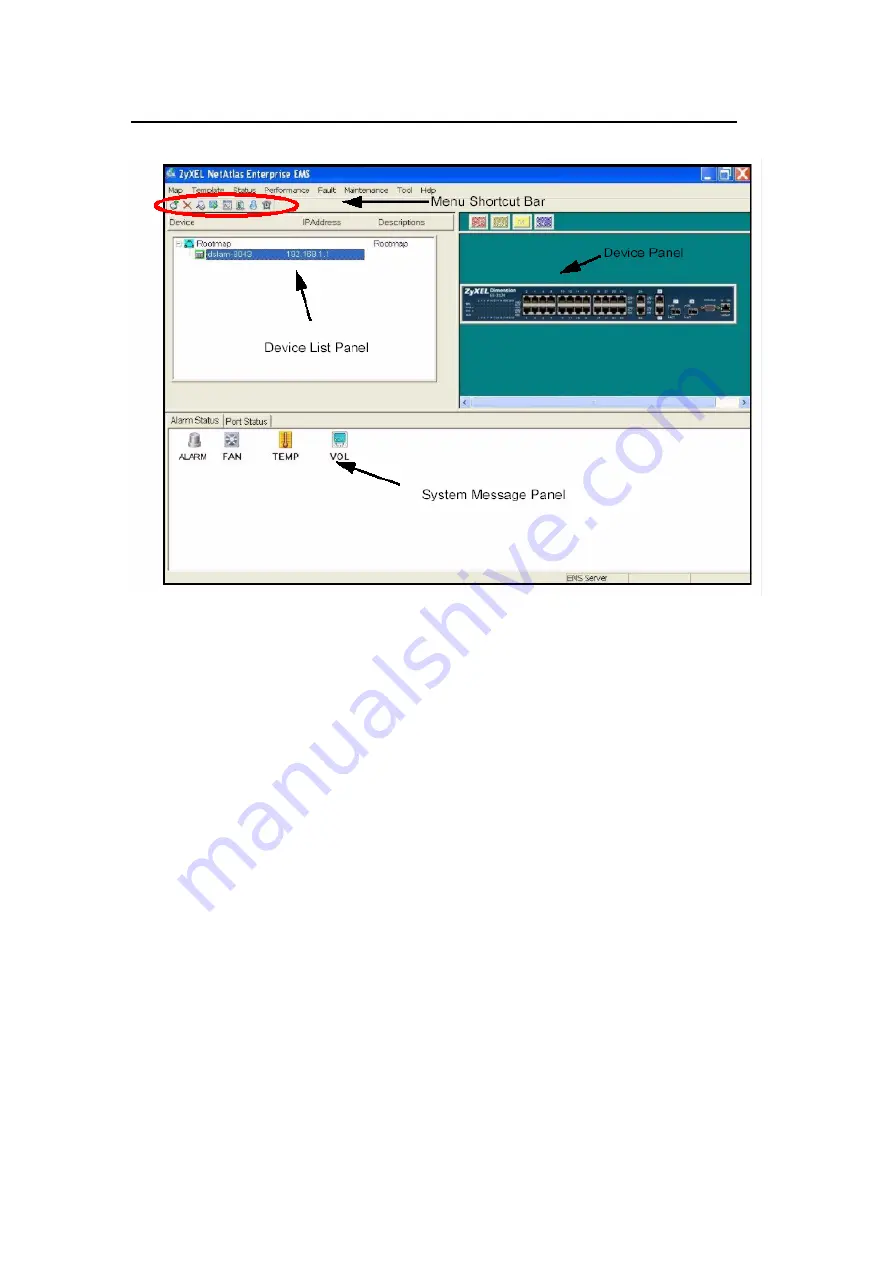
Page 20: ...stgreSQL an enterprise relational database system Figure 1 System Architecture SNMPc Overview The following figure shows the main screen elements of SNMPc z Main Button Bar Button and controls to execute commands quickly z Edit Button Bar Button to quickly insert map element z Event Log Tool Button display filtered event log entries z View Window Area Map View Mib Tables and Mib Graph windows are ...

Page 21: ...t Bar The buttons execute common commands z Device Panel This is a graphical device display z Device List Panel View devices in a tree structure The colors of the device indicate the status of the devices Green means the device is working properly and Red indicates no response from the device z System message Panel View the alarm and port status of the selected switch Figure 3 EMS Overview ...

Page 22: ...L Communications Corporation 21 Adding a new device in SNMPc This section shows you how to add a new device in SNMPc and access the EMS screen 1 In the edit button bar shown in Figure 4 click the Insert Device icon to create a new device node Figure 4 Adding a new Device ...

Page 23: ...mmunications Corporation 22 2 A Map Object Properties screen displays Enter a descriptive name in the Label field Then enter the IP address of the device in the Address field For this example we enter 192 168 0 1 as the IP address of the switch Figure 5 Map Object Properties ...

Page 24: ...ons Corporation 23 3 Click the Access tab to configure SNMP settings Change the value for Read Access Mode to SNMP V2c Figure 6 Read Access mode 4 Change the value for Read Write Access Mode to SNMP V2c Screen settings should be similar to the one shown Figure 7 Read Write Access Mode ...

Page 25: ...ZyXEL OLT 2300 Series Support Notes All contents copyright ٛ 2006 ZyXEL Communications Corporation 24 5 Change the value for Read Community to public Figure 8 Read Community ...

Page 26: ...ations Corporation 25 6 Change the value for Read Write Community to public Click OK to save the settings and close this screen Figure 9 Read write Community 7 In the Selection tool menu click the name of the OLT you have just created to manage the device Figure 10 Device Selection ...

Page 27: ... 8 A screen displays as shown Click Switch Manager to display the main EMS screen as shown in Figure 11 Figure 11 Device Selection 9 The device list panel on the left displays a logical hierarchy of the devices You can also see the devices added under the Rootmap in this list Figure 12 shows an example ...

Page 28: ... 2300 Series Support Notes All contents copyright ٛ 2006 ZyXEL Communications Corporation 27 10 Click on a switch icon to display the device panel and status screen as shown in Figure 13 Figure 13 Device mapping ...

Page 29: ...r in addition to making it possible to perform bidirectional communications over single fiber Below figure shows the WDM component which multiplexes de multiplexes different wavelengths to from single optical fiber The common port can carry different wavelengths and Pass port and Reflect port only can carry one wavelengths It will base on the specification of the vendor Below is an example to show...

Page 30: ...bers do not exhibit modal dispersion resulting from multiple spatial modes Single mode fibers are also better at retaining the fidelity of each light pulse over long distances than are multi mode fibers For these reasons single mode fibers can have a higher bandwidth than multi mode fibers Why do we need PON not point to point fiber network In order to bring the fiber network to a home in the past...

Page 31: ...iewed by many as an attractive solution to the first mile problem a PON minimizes the number of optical transceivers CO terminations and fiber deployment A PON is a point to multipoint P2MP optical network with no active elements in the signals path from source to destination The only interior elements used in PON are optical passive components such as optical fiber connectors splices and splitter...

Page 32: ...into multiple output fibers Higher split ratio means more ONUs can access the fiber The input optical power is normally split evenly between the output fibers What is splitter uniformity The optical loss between the input port and all N output ports of a 1 N splitter is ideally a constant In practice however the loss varies slightly from one port to another due to manufacturing issues This variati...

Page 33: ...optical splitter 7 4 dB max 1 8 splitting loss in a 1 8 optical splitter 10 5 dB max 1 16 splitting loss in a 1 16 optical splitter 14 dB max 1 32 splitting loss in a 1 32 optical splitter 17 5 dB max Fiber connector loss 0 2 0 3 dB z αis the fiber attenuation coefficient in dB km typically theα is 0 25dB km at 1550nm 1490nm and 0 35dB km at 1310nm z L is the fiber distance in km What is the power...

Page 34: ... use the typical value 0 3 dB 3 Splice loss The typical value of splice loss is around 0 1 0 5 dB We can use the average value 0 3 dB for this application note 4 Splitter loss Below is the splitter loss table for different splitter 1 2 splitting loss in a 1 2 optical splitter 3 6 dB max 1 4 splitting loss in a 1 4 optical splitter 7 4 dB max 1 8 splitting loss in a 1 8 optical splitter 10 5 dB max...

Page 35: ... 29dbm with 3 35dbm 2 65 6 Therefore at least 3 35dbm attenuation is needed for OLT Rx 2 Check if RX optical power in ONU is within ONU transceiver s dynamic range The dynamic range of ONU is 3dBm 26dBm and according to 1000BASE PX20 D the output power at the OLT side is 3dBm and the total loss is 6 55 dB ONU Rx power will be ONU Rx power max 3 6 65 3 65dBm The result shows the signal power at the...

Page 36: ...ill suggest the service provide to reserve 3 dB for the save margin 6 This step we will calculate the PON system support Power budget We need to check the specification for the OLT and ONU For OLT 1308 according to 1000BASE PX20 D the max output power is 3dbm and ONU 634HA 11 according to 1000BASE PX10 U the max output power is 4dbm The OLT receiver dynamic range is 6dBm 29dBm and the ONU receiver...

Page 37: ...rt COM1 COM2 or other COM port of your computer Launch terminal emulation software configured to the follow settings Terminal emulation VT100 Baud rate 115200 bps Data bits 8 Parity none Stop bit 1 Flow control none What is default login password for console telnet and FTP login Password 1234 How to change the password You can only change the administrator login password in the web configurato How...

Page 38: ...ug Mode within 3 seconds prompt 3 Enter atlc 4 When the starting XMODEM upload message displays start XMODEM upload of the default configuration rom file to the OLT 5 After the file upload process is complete enter atgo to exit from the debug mode 6 The system will automatically restart Wait until the system has restarted before you log in again The default IP address is 192 168 0 1 and the defaul...

Page 39: ...nd enter the show system information command This will display the firmware version the OLT is currently using Is the GEPON transceiver hot swappable No it is not hot swappable You can not change transceivers while the OLT is operating Is the mini GBIC transceiver hot swappable Yes it is hot swappable You can change transceivers while the OLT is operating Can I enable IGMP snooping on the OLT whic...

Reviews: