


IES-2500 User’s Guide
Hardware Troubleshooting
9-1
This chapter explains how to troubleshoot IES-2500 hardware. Refer also to the Troubleshooting
chapters in the card User’s Guides.
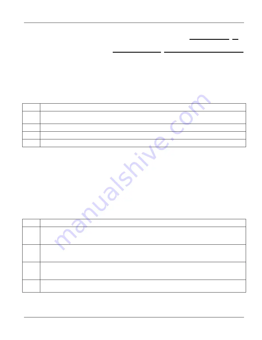
9.1 The SYS or PWR LED Does Not Turn On
Table 9-1 SYS LED Troubleshooting
STEP CORRECTIVE
ACTION
1
Make sure the power cord is properly connected and the power supply is operating normally. Make sure
you are using the correct power source (refer to the hardware specifications in the appendices).
2
Make sure the main chassis card is properly installed in the main chassis.
3
Make sure the power fuses are not burnt-out. Replace any burnt out fuses. Refer to
section 8.1
.
4
The LED itself or the unit may be faulty; contact your vendor.
9.2 The ALM LED Is On
The management switch card’s
ALM
(alarm) LED lights when an alarm has been detected on the management
switch card, the IES-2500 fan or the management switch card’s INPUT ALARM terminals. Examples of an alarm
on the management switch card are when the management switch card’s voltage or temperature is outside of the
normal range.
The
ALM
(alarm) LEDs on the DSL line cards light when the card is overheated and/or voltage readings are
outside the tolerance levels.
Table 9-2 ALM LED Troubleshooting
STEP CORRECTIVE
ACTION
1
Go to the
Hardware Monitor
screen in the web configurator to verify the cause of the alarm. See step 2 if
the unit is overheated, step 3 if the problem is with the fans and step 4 if the voltages are out of the
allowed ranges.
2
Ensure that the IES-2500 is installed in a well-ventilated area and that normal operation of the fans is not
inhibited. Keep the bottom, top and all sides clear of obstructions and away from the exhaust of other
equipment.
3
Make sure you can feel and/or hear the fans working - working fans emit a low buzz and blow air. If the
fans are not working properly, refer to the sections on the fan modules for instructions on changing a fuse
or changing the fan module.
4
If the voltage levels are outside the allowed range, take a screen shot of the
Hardware Monitor
web
configurator screen and contact your vendor.
Chapter 9
Hardware Troubleshooting
Summary of Contents for IES-2500
Page 1: ...IES 2500 Integrated Ethernet Switch Version 1 00 September 2003 User s Guide...
Page 6: ......
Page 12: ......
Page 14: ......
Page 19: ...IES 2500 User s Guide Card Installation 1 5 Figure 1 5 MTU Application Example...
Page 20: ......
Page 22: ......
Page 30: ......
Page 32: ......
Page 42: ......
Page 44: ......
Page 48: ......
Page 54: ......
Page 55: ...Appendices and Index V Part V Appendices and Index This part includes appendices and an index...
Page 56: ......
Page 58: ......