


16
parallel position with oval opening in control base plate 67
(fig. 2)
. Now the transmitter is adjusted for “closed”
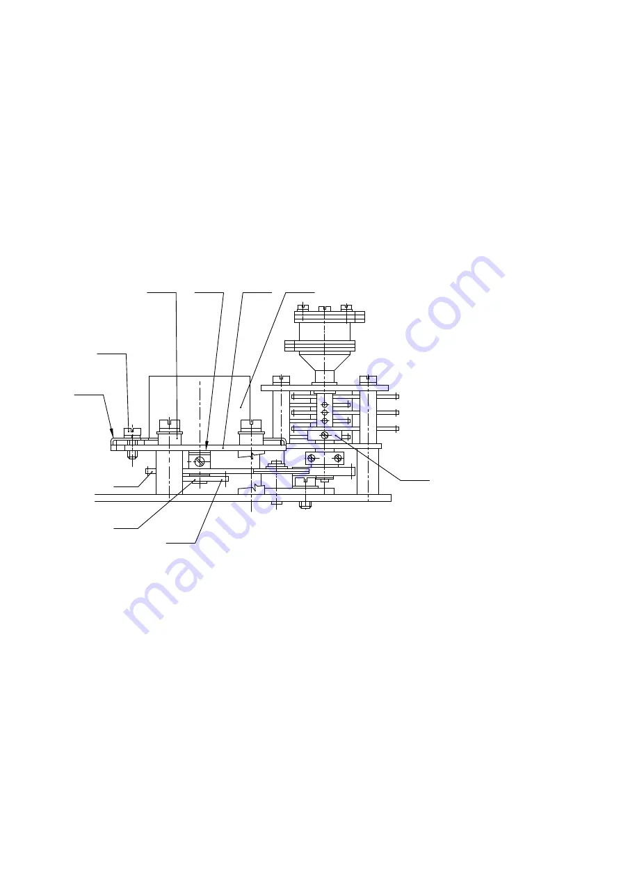
position. Afterwards, release screw 64
(fig. 7),
shift setting lever 65
(fig. 7)
towards transmitter up to dead stop
and retighten screw 64 again.
Now adjust actuator to “open” position, while transmitter indicator will move to a position between 0° and 160°.
Release screw 64 and turn setting lever 65 anticlockwise until the transmitter indicator reaches 160 °C sign. Subsequently
re-tighten screw 64 again and drop quick-drying ink on it to prevent it from releasing. Thus the transmitter is set to “open”
position. Position indicator is affixed to the axis of resistance transmitter 42
(fig. 8)
using screw 41. Release this screw
and, in “open position”, turn indicator in such a way that 100 sign on the scale of indicator -40- lines up with the colour
spot on the eye sight in the control box cover. Subsequently, tighten screw 41 and secure it in tightened position by
dropping quick-drying varnish on it.
Vishay resistance transmitter
Alternatively, actuators
MON can be equipped with a Vishay resistance transmitter. This transmitter has
a shaft led out on one side, with double wheel 73, consisting of toothed gears A and B, fixed on the end of the
shaft. The principle of drive and adjustment of Vishay transmitter is identical to current transmitter CPT 1Az.
The only difference consists in sizes of toothed gears A and B of double wheel 73, and thus also in table including
values for working stroke setting.
Adjustment of resistance position transmitter
First of all, it is necessary to set up suitable gear ratio between actuator output shaft and transmitter shaft as per
required working stroke of actuator – see table below.
To do this setting, use setting wheel K3 inside the transmission box of signalling unit as described under
point b) above. Further, you must bring the necessary gear of the double wheel, affixed on the transmitter shaft,
into meshing position. Gear with smaller diameter is identified as A, larger gear as B. Carry out alignment by
moving spacers 72 either below the transmitter bracket
(to make gear A mesh)
or above the transmitter bracket
(to make gear B mesh).
This must be done in a position when the transmitter bracket is in the furthermost
distance from the transmission box.
Afterwards, screws fixing the transmitter bracket must be slightly re-tightened to make possible for the transmitter
bracket to be moved to a position, when gear A or B is in meshing position with the driving gear. In this position, check
gears meshing and, when necessary, adjust the relative height of double wheel against the driving gear by means of
spacers on the transmitter shaft. A minor play must be maintained between gear A
(or B)
and the driving gear to prevent
transmitter shaft from strain in perpendicular direction to its axis. Now properly tighten the fixing screws of transmitter
bracket and secure them using varnish.
Select gear ratio for wheel K 3 and gears A, B using the following table. If the required working stroke lies in two
ranges at the same time, it is preferable to select the lower range.
Wheel on transmitter - gears
Description:
68 – resistance transmitter
69 – transmitter bracket
70 – locking screw
71 – adapter
72 – spacers
73 – double wheel
74 – spacer rings
B
A
73
72
70
71
74
69
K3
68
70
71
A
B
73
K3
68
69
72
74
Summary of Contents for 52 030
Page 2: ......
Page 50: ...NOTES...


