background image

Technical Reference Booklet

PIN 

SIGNAL           DESCRIPTION

VCC 

+5V/5VSB (optional)

-Data 0            Negative Data Channel 0

+Data0 

Positive Data Channel 0

GND 

Ground 

VCC 

+5V/5VSB (optional)

-Data 1 

Negative Data Channel 1

+Data 1 

Positive Data Channel 1

GND 

Ground

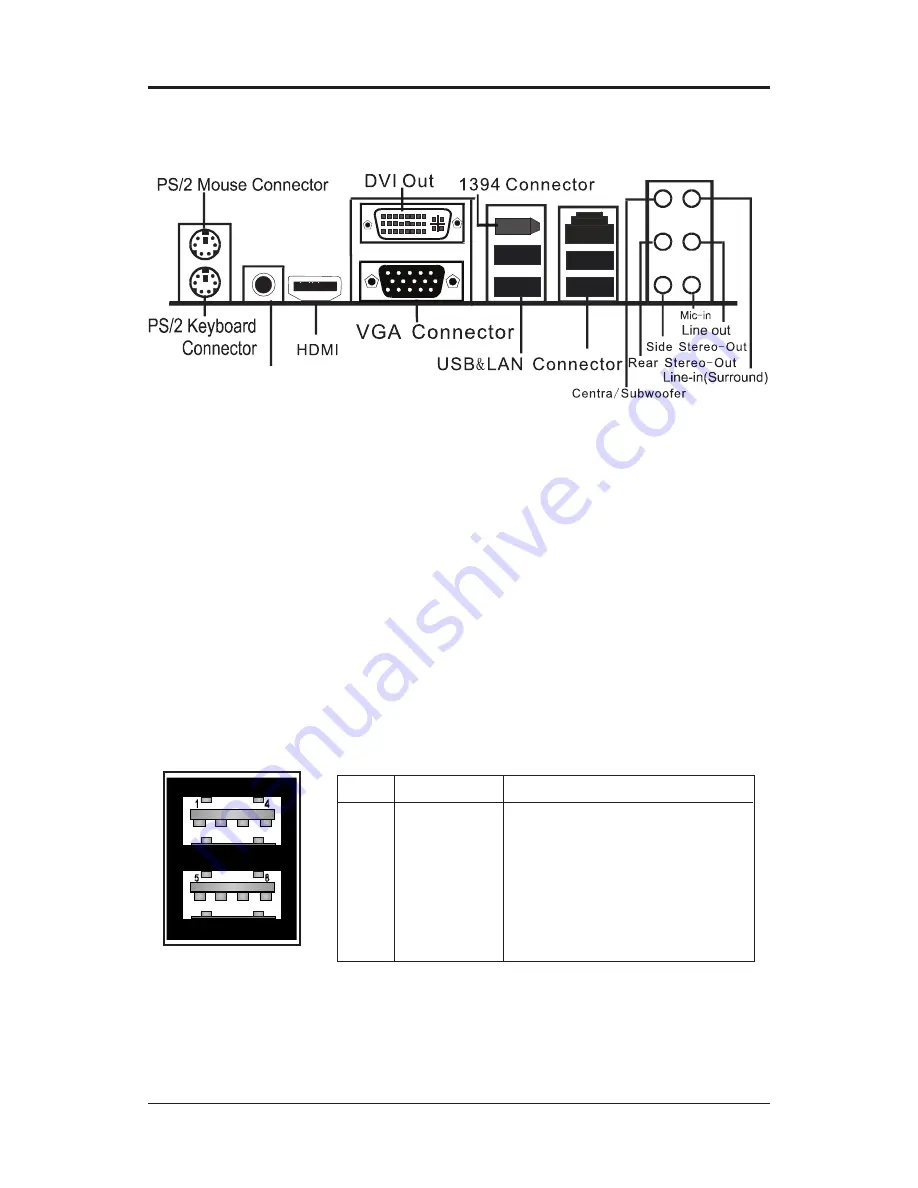
rear panel

The back panel provides the following connectors:

Mouse Connector

The motherboard provides a standard PS/2

® 

 mouse mini DIN connector for

attaching  a  PS/2

®   

mouse.  You  can  plug  a  PS/2

® 

  mouse  directly  into  this                   

connector.

Keyboard Connector

The motherboard provides a standard PS/2

® 

 keyboard mini DIN connector for 

attaching a PS/2

®  

keyboard. You can plug a PS/2

® 

 keyboard directly into this 

connector.

usb 2.0 Connector

The  motherboard  provides  a  UHCI  (Universal  Host  Controller  Interface)                     

Universal Serial Bus root for attaching USB devices such as keyboard, mouse 

or other  USB-compatible devices. You can plug the USB device directly into 

the connector.

usb 2.0 Connector description

usb 2.0 Connector

SPDIF OUT

Summary of Contents for NVIDIA MCP73U

Page 1: ...THE EQUIPMENT AND THE RECEIVER CONNECT THE EQUIPMENT INTO AN OUTLET ON A CIRCUIT DIFFERENT FROM THAT OF THE RECEIVER CONSULT THE DEALER OR AN EXPERIENCED AUDIO TELEVISION TECHNICIAN NOTE Connecting th...

Page 2: ...ower Connectors CPU FAN SYS FAN1 SYS FAN2 optional 13 Front Panel Audio Header FP_S1 14 USB Connectors FP_U1 FP_U2 FP_U3 optional 15 IEEE1394 Connectors CN4 optional 16 SPDIF In Out Header CN7 optiona...

Page 3: ...nd Effect 32 Environment Simulation 32 Equalizer Selection 33 Frequently Used Equalizer Setting 33 Karaoke Mode 33 Mixer 34 Playback control 34 Recording control 35 Audio I O 36 Speaker Configuration...

Page 4: ...800 SDRAM memory types 1 8V DRAM interface for DDRII SDRAM Onboard I O Onboard one PCI fast IDE port supporting up to 2 ATA ATA2 Ultra ATA33 66 100 133 IDE HDDs CD ROMs ZIP drives and LS 120 drives as...

Page 5: ...grated Realtek ALC888 controller Full Direct Sound and Sound Blaster compatibility Full Duplex 4 24 bit two channel DACs and 3 stereo 20 bit ADCs PnP and APM 1 2 support Windows 2000 XP Vista ready Su...

Page 6: ...aphics interface One X16 slot PCI Express graphics port Fully compliant with the PCI Express Base Specification revision 1 0a The base PCI Express frequency of this interface is 4GB s PCI Express supp...

Page 7: ...o check the HDD cable orientation in order to match the colored strip to the pin 1 end of the connector 2 When you start up the system please wait for 5 seconds after you power on AC 3 Adding a metal...

Page 8: ...i DIN connector for attaching a PS 2 mouse You can plug a PS 2 mouse directly into this connector Keyboard Connector The motherboard provides a standard PS 2 keyboard mini DIN connector for attaching...

Page 9: ...rts Enhanced Parallel Port EPP and Extended Capabilities Parallel Port ECP mode 8 Channel HD Audio optional Option select of 2 6 or 8 channel audio from onboard High Definition compliant CODEC with 20...

Page 10: ...peed change will be seen even if the frequency multiplier setting in CMOS setup is changed Jumper Setting This chapter explains how to configure the motherboard s hardware Before us ing your computer...

Page 11: ...drive connector that supports 360K 720K 1 2M 1 44M and 2 88M floppy disk types Hard Disk Connectors CN1 The motherboard has a 32 bit Enhanced PCI IDE and Ultra DMA 66 100 133 controller that provides...

Page 12: ...SATA4 Each supports 2nd generation serial ATA data rates of 300MB s All connector types are fully compliant with Serial ATA 2 0 specifications Each Serial ATA connector can connect to 1 hard disk dev...

Page 13: ...wire to the connectors always take note that the red wire is the positive and should be connected to the 12V the black wire is Ground and should be connected to GND If the motherboard has a System Ha...

Page 14: ...sis must have front audio connector Also please make sure the pin assignment on the cable is the same as the pin assignment on the mainboard header To find out if the chassis you are buying supports a...

Page 15: ...the front of the case If you have this kind of case use the auxiliary USB connectors FP_ U1 FP_U2 FP_U3 to connect the front mounted ports to the motherboard PIN Assignment 1 VCC 2 VCC 3 USBP0 4 USBP...

Page 16: ...rboard provides one 1394 pin headers that allow you to connect IEEE 1394 ports IEEE 1394 Cable optional CN4 Pin Definition PIN Assignment 1 TPA 2 TPA 3 Ground 4 Ground 5 TPB 6 TPB 7 Cable power 8 Cabl...

Page 17: ...ides a SPDIF Sony Philips Digital Interface Input output to digital multimedia device through fiber or coaxial connector CN7 Pin Definition PIN Assignment 1 SPDIF out 2 SPDIF in 3 3 3V 4 3 3V 5 NC 6 N...

Page 18: ...18 Technical Reference Booklet CD IN Connector CD1 optional The connector is for CD ROM Drive PIN Assignment 1 CD L 2 GND 3 GND 4 CD R CD1 Pin Definition 1 CD1 LGA775 Socket FOXCONN REM OVE...

Page 19: ...19 Front Panel Header FP1 The motherboard provides one front panel connector RESET GND HDD_LED HDD_LED FP1 NC PWR_SW KEY PW_LED 7 9 5 3 1 6 8 10 2 4 GND PW_LED LGA775 Socket FOXCONN REM OVE...

Page 20: ...nect Slots The PCI slots allow you to insert expansion cards to meet your needs When adding or removing expansion cards make sure that you unplug the power supply first Read the documentation for the...

Page 21: ...r and thumb to move metal lever so it is separated from the bottom steel shell grip hook 2 Use index finger to lift the top steel 3 Use index finger and thumb to place the CPU onto the plastic body lo...

Page 22: ...teel shell grip hook 6 It s recommended that the CPU heatsink should be an approval by Intel corporation design for Prescott CPU Choose the orientation of the thermal solution for optimal wire routing...

Page 23: ...he motherboard holes with no insertion force 8 Engage the fasteners caps Apply thumb pressure to the top of each of the 4 fastener caps there is no specific order of engagement you will hear a click u...

Page 24: ...echnical Reference Booklet MEMORY CONFIGURATIONS DDRII DIMM Sockets Location Please refer to the following figure for the location of the DDRII DIMM Sock ets DDRII 1 DDRII 2 LGA775 Socket FOXCONN REM...

Page 25: ...DIMM module above the socket and align the notch in the bottom edge of the module with the key in the socket 4 Insert the bottom edge of the DDRII DIMM module into the socket 5 When the module is seat...

Page 26: ...agement features The settings made in the Setup Utility affect how the computer performs Before using the Setup Utility ensure that you understand the Setup Utility options This chapter provides expla...

Page 27: ...e Date Hard Disk Type Note The sample BIOS Setup Menu included here only shows a typical case and may not be exactly the same as the one on your unit Note that a brief description of each highlighted...

Page 28: ...hanges and exits setup Saving Standard CMOS Features The items in Standard CMOS Setup Menu are divided into 10 categories Each category includes one or more setup items Use the arrow keys to highlight...

Page 29: ...se registers control most of the system options in the computer This section allows you to configure the system based on the specific features of the installed chipset This chipset manages bus speeds...

Page 30: ...selected Setup at Security Option from BIOS Features Setup menu you will be prompted for the password only when you enter BIOS Setup Supervisor Password has higher priority than User Password You can...

Page 31: ...Enter the file name of the new BIOS 5 The question Do you want to save BIOS Y N is displayed Press N if there is no need to save the existing BIOS Press Y if a backup copy of the existing BIOS is need...

Page 32: ...nd the control panel will appear Sound Effect After clicking on the Sound Effect tab 3 sections Environment Equalizer and Karaoke are available for selection Environment Simulation You will be able to...

Page 33: ...r quick enjoyment How to Use Other than the buttons Pop Live Club Rock shown on the page to pull down the arrow in Others you will find more optimized settings available to you Karaoke Mode Karaoke mo...

Page 34: ...you to create your favorite sound effect in one single tool Playback control Mute You may choose to mute single or multiple volume controls or to completely mute sound output Tool Show the following...

Page 35: ...multiple volume controls or to completely mute sound input Tool Show the following volume controls This is to let you freely decide which volume control items to be displayed Advanced controls Advance...

Page 36: ...functions Instead now each jack is able to be chosen to perform either output i e playback func tion or input i e Recording function we call this Retasking Audio I O aims to help you setting jacks as...

Page 37: ...for your selection Please select the device you are trying to plug in If the device is being plugged into the correct jack you will be able to find the icon beside the jack changed to the one that is...

Page 38: ...re so called AC 97 jacks If so please check this item to disable front panel jack detection Enable auto popup dialogue when device has been plugged in Once this item checked the dialog Connected devic...

Page 39: ...successfully caught by codec Sampling Rate Data Validation This indicates if the input data is known to Realtek HD Audio Manager Copyright protection The input data can only be copied while Copy Free...

Page 40: ...ou will get the best quality if you chose 90 position which we recommend you to use this effectively means that you speak right into the microphone Note A Stereo Microphone is required when using Beam...

Page 41: ...ion 3DAudio Demo grants you another possibility to enjoy your sound The Audio Demo allows you to listen to sound in an extraordinary way Information This section provides information about your curren...

Page 42: ...anual Setting up the BIOS 1 Setting your computer then press Delete to enter the Bios setup The BIOS CMOS Setup Utility window appears 2 Use the arrow keys to select Integrated Peripherals then press...

Page 43: ...ars 4 From the RAID Config window enable RAID then enable the disks that you want to use as RAID disks 5 Press F10 to save the configuration and exit The PC reboots 6 Enter the RAID BIOS Setup by pres...

Page 44: ...If RAID 0 Striping is selected you can manually set the striping block size in the Striping Block field use the UP or DOWN ARROW ey to set the Striping Block size The KB is standard unit of Striping...

Page 45: ...rives press Y If the hard drives contain previously created RAID array you need to press Y to clear the data from the hard drives 7 After that then Array List screen displaying the RAID array you crea...

Page 46: ...ze disk model name and disk capacity etc 9 To delete the array press D in the Array Detail screen When the Delete this array message appears press Y to confirm or N to cancel Press ENTER to return to...

Page 47: ...Installing the RAID Drivers 1 After you complete the RAID BIOS setup boot from the windowsxp CD The Windows Setup program starts 2 Press F6 and wait a few moments for the Windows Setup screen to ap pe...

Page 48: ...48 Technical Reference Booklet 3 Specify the NVIDIA drivers 1 Insert the floppy that has the RAID driver press S then press Enter 2 Select NVIDIA RAID CLASS DRIVER and then press Enter...

Page 49: ...oppy disk inserted in the floppy drive until the blue screen portion of Windows XP installation is completed then take out the floppy 5 Follow the instructions on how to install Windows XP During the...

Page 50: ...50 Technical Reference Booklet...

Page 51: ...51...

Page 52: ...52 Technical Reference Booklet U 219DA8...

Reviews: