background image

8


Intel H55-ITX series Motherboard 

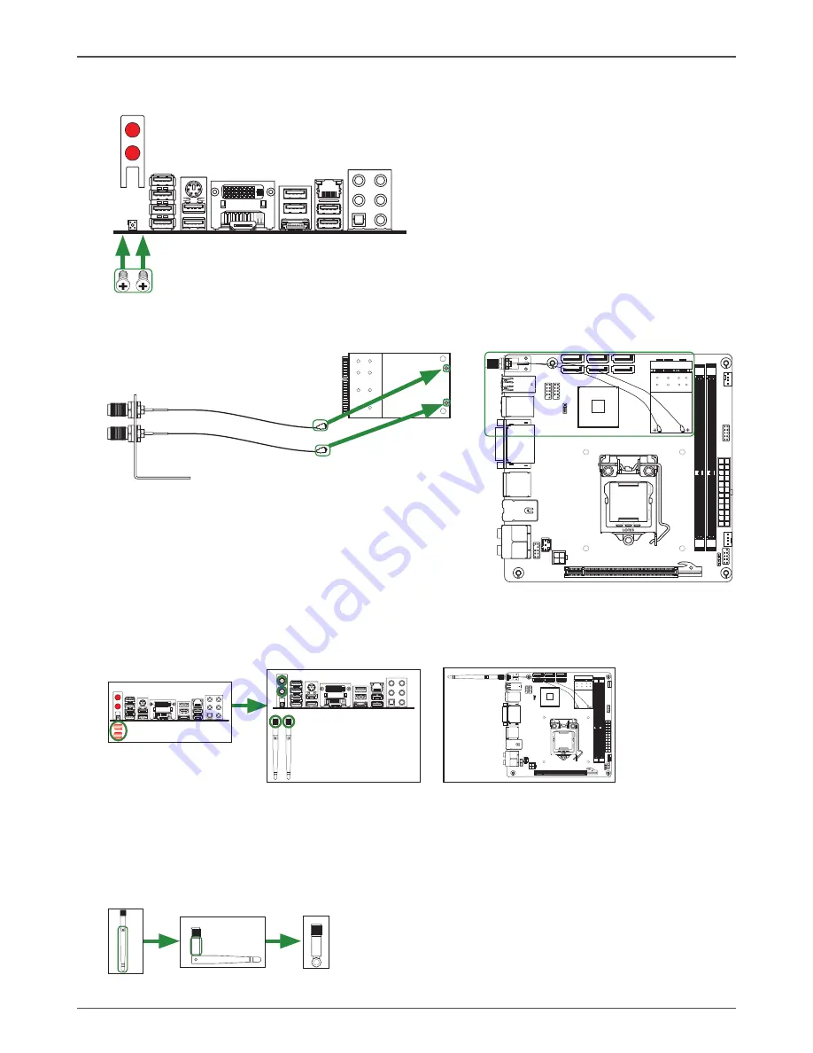
       Step 4. Remove the red caps from the WiFi antenna connectors. 
                       Install the WiFi antennas to the WiFi antenna connectors, and make sure the screws 
                    are rotated in clockwise direction.

Note: 1. Users please note that the appearance of your WiFi antenna modules may   
              not be exactly the same as those shown in this manual.
          2. Users can install one or two WiFi antennas to the motherboard.
          3. Users can bend or rotate the WiFi antennas to the best receiving direction 
              according to the picture below.

       Step 2. Secure the bracket to the motherboard with screws according to the picture below.

12

0

24

0

12

1

12

0

24

0

12

1

1

.5

V

1

.5

V

115XLM

L

G
A

1

1

5

6

REMOVE

L

O
T

E

S

        Step 3. Connect the WiFi wires to the MINI PCIE card as the following picture shows.

MINI PCIE card

Bracket

WiFi wires

12

0

24

0

12

1

12

0

24

0

12

1

1

.5

V

1

.5

V

115XLM

L

G
A

1

1

5

6

REMOVE

L

O
T

E

S

Screws

Bracket

Summary of Contents for H55 - ITX wifi series

Page 1: ......

Page 2: ...CONNECT THE EQUIPMENT INTO AN OUTLET ON A CIRCUIT DIFFERENT FROM THAT OF THE RECEIVER CONSULT THE DEALER OR AN EXPERIENCED AUDIO TELEVISION TECHNICIAN NOTE Connecting this device to peripheral devices...

Page 3: ...4 4 pin ATX_12V power connector PW2 14 SPDIF Out Header CN5 15 COM Header CN4 Optional 15 Front panel header FP1 15 USB Headers FP_U1 FP_U2 16 Front Pannel Audio Header FP_S1 16 Speaker Header SPK1 17...

Page 4: ...llation 28 Realtek HD Audio Driver Setup 39 Getting Started 39 Sound Effect 39 Environment Simulation 39 Equalizer Selection 40 Frequently Used Equalizer Setting 40 Karaoke Mode 40 Mixer 41 Playback c...

Page 5: ...orts ten optional ports on the back panel four via the USB brackets connected to the internal USB headers v Supports USB 2 0 protocol up to 480 Mbps transmission rate q Onboard Serial ATA ports v Inde...

Page 6: ...power failure recovery q Onboard Graphics Features v DX10 and OpenGL 2 0 are supported v 3D Graphics Rendering Enhancements v Up to 2048x1536 75 Hz refresh v HDMI DVI port output support DVI VGA adapt...

Page 7: ...the motherboard and Figure 2 shows the back panel connectors Figure 1 Board Layout 1 SYS Fan Connector SYSFAN1 2 COM Header_CN4 Optional 3 24 pinATX Power Connector PW1 4 CPU Fan Connector_CPUFAN1 5 F...

Page 8: ...Port with LEDs to indicate status Yellow Light Up Blink 10 Mbps Link Activity Yellow and Green Light Up Blink 100 Mbps link Activity Yellow and Orange Light Up Blink 1000 Mbps link Activity 9 DVI Por...

Page 9: ...n this manual 2 Users can install one or two WiFi antennas to the motherboard 3 Users can bend or rotate the WiFi antennas to the best receiving direction according to the picture below Step 2 Secure...

Page 10: ...the CPU fan v Installing Memory DIMMs q Installing the motherboard q Connecting cables and setting switches Safety Instructions To reduce the risk of fire electric shock and injury always follow basi...

Page 11: ...U installtaion components 1 Unhook the socket lever by pushing down and away from the socket 2 Lift the socket lever and the load plate to fully open position 3 Use your thumb and forefinger to lift t...

Page 12: ...install memory DIMMs q One DIMM Install it into slot 1 or 2 You can install the DIMM into any slot however slot 1 is preferred q Two DIMMs Install them into slot 1 and slot 2 Refer to the following p...

Page 13: ...from dust and foreign objects and promotes correct airflow within the chassis Before installing the motherboard install the I O shield from the inside of the chassis Press the I O shield into place a...

Page 14: ...Connector PW1 v 4 pin ATX_12V Power Connector PW2 q Internal Headers Connectors v SPDIF Out Header CN5 v COM Header CN4 Optional v Front Panel Header FP1 v USB Header FP_U1 FP_U2 v Front Pannel Audio...

Page 15: ...efinition Pin Signal Pin Signal 1 3 3V 13 3 3V 2 3 3V 14 12V 3 GND 15 GND 4 5V 16 PS_ON 5 GND 17 GND 6 5V 18 GND 7 GND 19 GND 8 PWROK 20 5V 9 5V_AUX 21 5V 10 12V 22 5V 11 12V 23 5V 12 3 3V 24 GND 4 pi...

Page 16: ...hese two pins The HDD indicator LED indicates the activity status of the hard disks q RST SW Attach the Reset switch cable from the front panel of the case to these two pins The system restarts when t...

Page 17: ...ds of audio output choices the Front Audio the Rear Audio The front Audio supports retask ing function Note In order to utilize the front audio header your chassis must have front audio connector Also...

Page 18: ...e There are six serial ATA connectors on the motherboard that support AHCI configuration SPK1 Pin Definition PIN Assignment 1 VCC 2 NC 3 NC 4 SPK SATA Pin Definition Pin Signal 1 GND 2 TXP 3 TXN 4 GND...

Page 19: ...re set correctly Refer to this section whenever in doubt CMOS Clear Jumper JP1 Close Open Default setting If you want to clear the system configuration use the JP1 Clear CMOS Jumper to clear data Noti...

Page 20: ...Test POST Pressing Del takes you to the BIOS Setup Utility Note 1 We reserve the right to update the BIOS version presented in the manual The BIOS pictures shown in this section are for reference only...

Page 21: ...ection including the required data If you enable this item two lines will be prefetched whether there is required data or not q MPS and ACPI MADT ordering Use this item to set MPS and ACPI MADT orderi...

Page 22: ...iguration The items allow you to configure SATA 1 2 q Primary Second Third and Fourth IDE Master Slave This displays the status of auto detection of IDE devices q Hard Disk Write Protect This item wil...

Page 23: ...t in BIOS USB Configuration The items in this menu allow you to change the USB related features Press enter To display the configuration options q Legacy USB Support Allows you to enable or disable su...

Page 24: ...during system boot q Plug and Play O S When set to No BIOS configure all the devices in the system When set to YES and if you install a Plug and Play operating system the operating system configures...

Page 25: ...set the Interrupt Request q DMA Channel 0 1 3 5 6 7 Use these items to set the Direct Memory Access Channel q Reserved Memory Size This item allows you to set the size of memory block to reserve for...

Page 26: ...e supervisor user password The Supervisor User Password item on top of the screen shows the default setting Not Installed After you set a password this item shows Installed To set a Supervisor User Pa...

Page 27: ...e features including Memory Graphic NB PCIE and so on South bridge Configuration The item allows you to configure south bridge features including USB HDA SMBUS and so on ME Subsystem Configuration The...

Page 28: ...tup menus When you select this option a confirmation window appears Select Ok to load default values Select Cancel to make other changes before saving the values to the non volatile RAM Load Failsafe...

Page 29: ...rivers and additional INTEL software The CD that has been shipped with your Intel H55 motherboard contains the following software and drivers q Intel chipset Driver q HDA Sound driver q Intel Graphics...

Page 30: ...29 Installing Drivers And Software 2 Left click Intel chipset Driver begin loading Note If the MINI PCIE card is installed the option Atheros Wireless driver will display as the following window...

Page 31: ...30 Intel H55 ITX series Motherboard 3 Left click HDA sound driver begin loading...

Page 32: ...31 Installing Drivers And Software 4 Left click Intel Graphics Driver begin loading...

Page 33: ...32 Intel H55 ITX series Motherboard...

Page 34: ...33 Installing Drivers And Software 5 Left click JMB36X driver begin loading...

Page 35: ...34 Intel H55 ITX series Motherboard 6 Left click Intel R PRO Network Driver the following notepad will guide you to install Intel PRO network driver...

Page 36: ...35 Installing Drivers And Software Follow the steps below to install Intel R PRO Network Driver...

Page 37: ...36 Intel H55 ITX series Motherboard...

Page 38: ...37 7 Left click Atheros Wireless driver begin loading Installing Drivers And Software...

Page 39: ...38 Intel H55 ITX series Motherboard At last you can enter Computer Management that provides information about the hardware devices on this motherboard to check if the driver installation is complete...

Page 40: ...ar Sound Effect After clicking on the Sound Effect tab 3 sections Environment Equalizer and Karaoke are available for selection Environment Simulation You will be able to enjoy different sound experie...

Page 41: ...ntly used for your quick enjoyment How to Use Other than the buttons Pop Live Club Rock shown on the page to pull down the arrow in Others you will find more optimized settings available to you Karaok...

Page 42: ...o you to create your favorite sound effect in one single tool Playback control Mute You may choose to mute single or multiple volume controls or to completely mute sound output Tool Show the following...

Page 43: ...mute single or multiple volume controls or to completely mute sound input Tool Show the following volume controls This is to let you freely decide which volume control items to be displayed Advanced...

Page 44: ...Instead now each jack is able to be chosen to perform either output i e playback function or input i e Recording function we call this Retasking Audio I O aims to help you setting jacks as you wish M...

Page 45: ...op up for your selection Please select the device you are trying to plug in If the device is being plugged into the correct jack you will be able to find the icon beside the jack changed to the one th...

Page 46: ...o called AC 97 jacks If so please check this item to disable front panel jack detection Enable auto popup dialogue when device has been plugged in Once this item checked the dialog Connected device wo...

Page 47: ...VD Audio Output Source Output digital audio source The digital audio format such as wav mp3 midi etc will come out through S PDIF Out Speaker Calibration After you have successfully plugged in speaker...

Page 48: ...You will get the best quality if you chose 90 position which we recommend you to use this effectively means that you speak right into the microphone Note A Stereo Microphone is required when using Be...

Page 49: ...mo The section 3DAudio Demo grants you another possibility to enjoy your sound TheAudio Demo allows you to listen to sound in an extraordinary way Information This section provides information about y...

Page 50: ......

Reviews: