background image

8


GeForce 8100/8200/8300-ITX series Motherboard 
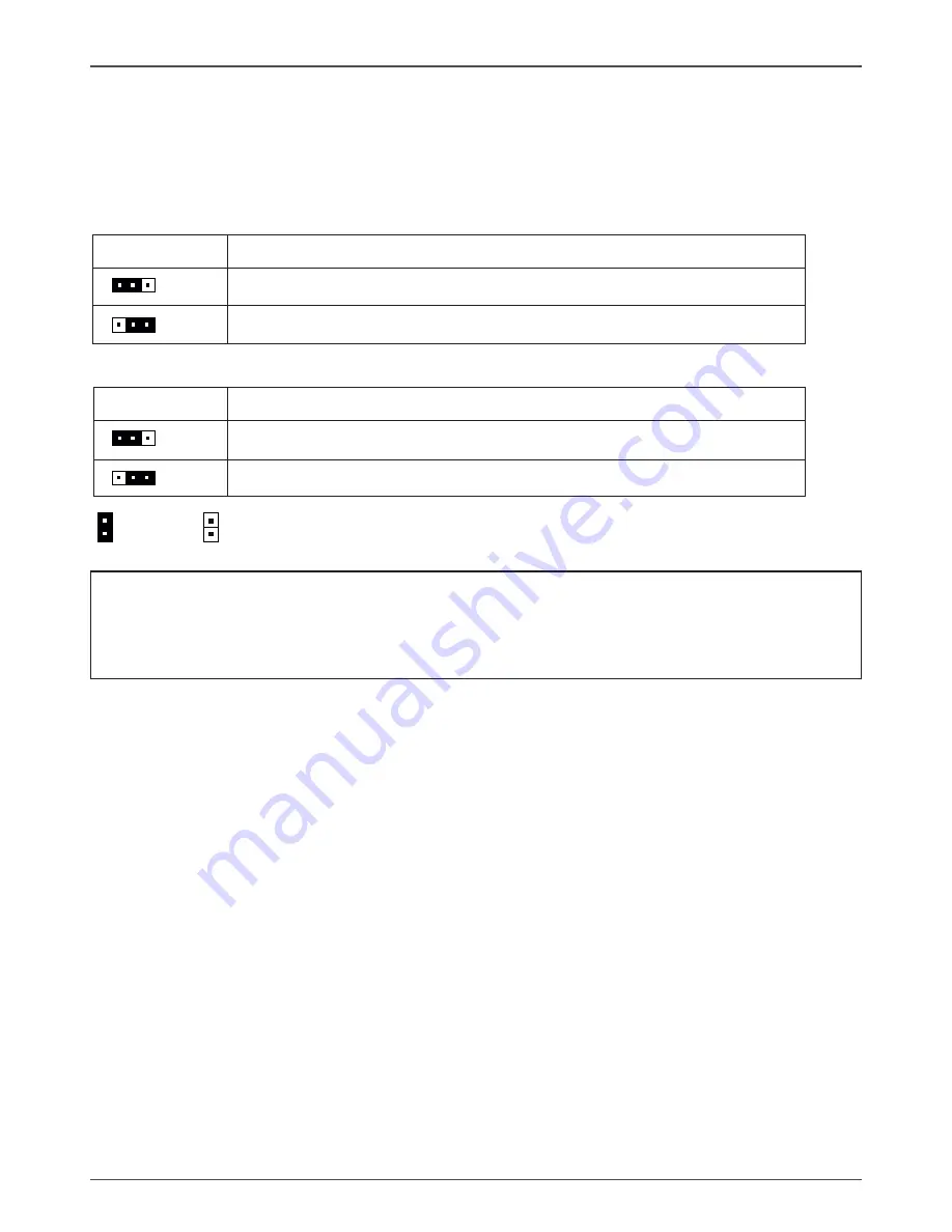
 

JPUSB  


Selection


 1-2* 


5V power input


               2-3 


5V standby power input 


JH   

Selection


 1-2* 


Normal*


               2-3 


CMOS Clear 

Jumper Setting

This chapter explains how to configure the motherboard’s hardware. Before using your 

computer, make sure all jumpers and DRAM modules are set correctly. Refer to this 

chapter whenever in doubt. 

Notice

:

Be sure to save the CMOS setting when exit the CMOS.

If the CPU is frequency multiplier locked, no CPU speed change will be seen 

even if the frequency multiplier setting in CMOS setup is changed.

1.

2.

       Close                Open         *  Default setting.

JH-CMOS Clear

JPUSB-Rear USB Power Selection

Summary of Contents for GeForce 8100-ITX series

Page 1: ......

Page 2: ...ONNECT THE EQUIPMENT INTO AN OUTLET ON A CIRCUIT DIFFERENT FROM THAT OF THE RECEIVER CONSULT THE DEALER OR AN EXPERIENCED AUDIO TELEVISION TECHNICIAN NOTE Connecting this device to peripheral devices...

Page 3: ...And Setting Switches 11 20 pin ATX Power ATXPWR 12 4 pin ATX 12V Power ATX12V1 12 SPDIF Out Header 13 Speaker Connector SPK 13 Front Panel Header 14 USB WIFI Headers 15 FP Audio Connector 15 Fan Conn...

Page 4: ...dio I O 31 Speaker Configuration 32 Connector Settings 33 S PDIF 33 Speaker Calibration 34 Microphone 35 Noise Suppression 35 Beam Forming 35 Acoustic Echo Cancellation 35 Audio Demo 36 Information 36...

Page 5: ...l up to 480 Mbps transmission rate q Onboard Serial ATA II v Independent DMA operation on four ports optional v Data transfer rates of 300Mb s q Onboard LAN v LAN interface built in onboard v Supports...

Page 6: ...el Connectors Rear USB Power Selection Jumper 4 pinATX_12V power Connector CPU Socket DDRII DIMM Socket 10 11 12 13 14 15 16 17 Figure 1 Board Layout Figure 1 shows the motherboard and Figures 2 shows...

Page 7: ...Pink Mic In Mic In Center Subwoofer 7 Lan Port with LEDs to indicate status Green Light Up Blink 10 Mbps Link Activity Orange Light Up Blink 100 Mbps Link Activity Orange Light UP Blink 1000 Mbps Link...

Page 8: ...ng the CPU v Installing the CPU fan v Installing the memory q Installing the motherboard q Connecting cables and setting switches Safety Instructions To reduce the risk of fire electric shock and inju...

Page 9: ...ar row should point away from the lever pivot The CPU can only sit properly in the socket in the correct orientation If the CPU is correctly seated the pins should be completely embedded in the socket...

Page 10: ...y See Figure 1 on page 5 for the location of the memory slots q One DIMM You can install the DIMM into any slot q Two DIMMs Install into slots 1 and 2 The idea is to run on dual channel mode Use the f...

Page 11: ...rboard into the chassis Note Be sure that the CPU fan assembly has enough clearance for the chassis covers to lock into place and for the expansion cards Also make sure the CPU Fan assembly is aligned...

Page 12: ...onnecting Cables and Setting Switches This section takes you through all the connections and switch settings necessary on the motherboard See Figure 1 to locate the connectors and jumpers referenced i...

Page 13: ...s secure Table 1 ATXPWR Pin Assignments Connector Pin Signal Pin Signal 1 3 3V 11 3 3V 2 3 3V 12 12V 3 GND 13 GND 4 5V 14 PS_ON 5 GND 15 GND 6 5V 16 GND 7 GND 17 GND 8 PWROK 18 5V 9 5V_AUX 19 5V 10 12...

Page 14: ...ny Philips Digital Interface to digital multimedia device through coaxial connector SPDIF Pin Definition PIN Assignment 1 SPDIF out 2 3 3V 3 NC 4 GND PIN Assignment 1 VCC 2 NC 3 NC 4 SPK SPK Pin Defin...

Page 15: ...e connectors to the corresponding pins q PWR SW Attach the power button cable from the case to these two pins Pressing the power button on the front panel turns the system on and off rather than using...

Page 16: ...ndard and provides two kinds of audio output choices the Front Audio the Rear Audio The front Audio supports re tasking function Note In order to utilize the front audio header your chassis must have...

Page 17: ...e 12V GND Connecting Serial ATA Cables SATA 1 SATA 4 The SerialATAII connector is used to connect the Serial ATA II device to the motherboard These connectors support the thin Serial ATA II cables for...

Page 18: ...ss slot x1 PCI Express x1 Slots optional There is one PCI Express x1 slot that is designed to accommodate less bandwidth intensive cards such as a modem or LAN card The x1 slot provides 500 MB sec ban...

Page 19: ...s hardware Before using your computer make sure all jumpers and DRAM modules are set correctly Refer to this chapter whenever in doubt Notice Be sure to save the CMOS setting when exit the CMOS If th...

Page 20: ...nagement features The settings made in the Setup Utility affect how the computer performs Before using the Setup Utility ensure that you understand the Setup Utility options This chapter provides expl...

Page 21: ...F10 Save Exit Setup Time Date Hard Disk Type Note The sample BIOS Setup Menu included here only shows a typical case and may not be exactly the same as the one on your unit Note that a brief descripti...

Page 22: ...Exit Without Abandons all CMOS value changes and exits setup Saving Standard CMOS Features The items in Standard CMOS Setup Menu are divided into 10 categories Each category includes one or more setu...

Page 23: ...e chipset registers These registers control most of the system options in the computer This section allows you to configure the system based on the specific features of the installed chipset This chip...

Page 24: ...ity Option from BIOS Features Setup menu you will be prompted for the password only when you enter BIOS Setup Supervisor Password has higher priority than User Password You can use Supervisor Password...

Page 25: ...type AWDFLASH ENTER 4 Enter the file name of the new BIOS 5 The question Do you want to save BIOS Y N is displayed Press N if there is no need to save the existing BIOS Press Y if a backup copy of th...

Page 26: ...n your system setup the install disk may automatically run the install setp exe and pop up a menu If it does not run go to My Computer and click on the CD to open Usually you should install the Nvidia...

Page 27: ...00 ITX series Motherboard HDMI SETUP You can connect HDMI device to DVI port by a DVI HDMI dongle Enter Control Panel double click Sounds andAuddio Devices select NVIDIA HDMI Audio as default play bac...

Page 28: ...ar Sound Effect After clicking on the Sound Effect tab 3 sections Environment Equalizer and Karaoke are available for selection Environment Simulation You will be able to enjoy different sound experie...

Page 29: ...frequently used for your quick enjoyment How to Use Other than the buttons Pop Live Club Rock shown on the page to pull down the arrow in Others you will find more optimized settings available to you...

Page 30: ...o you to create your favorite sound effect in one single tool Playback control Mute You may choose to mute single or multiple volume controls or to completely mute sound output Tool Show the following...

Page 31: ...oose to mute single or multiple volume controls or to completely mute sound input Tool Show the following volume controls This is to let you freely decide which volume control items to be displayed Ad...

Page 32: ...in functions Instead now each jack is able to be chosen to perform either output i e playback function or input i e Recording function we call this Retasking Audio I O aims to help you setting jacks a...

Page 33: ...cted device will pop up for your selection Please select the device you are trying to plug in If the device is being plugged into the correct jack you will be able to find the icon beside the jack cha...

Page 34: ...e so called AC 97 jacks If so please check this item to disable front panel jack detection Enable auto popup dialogue when device has been plugged in Once this item checked the dialog Connected device...

Page 35: ...ying DVD Audio Output Source Output digital audio source The digital audio format such as wav mp3 midi etc will come out through S PDIF Out Speaker Calibration After you have successfully plugged in s...

Page 36: ...You will get the best quality if you chose 90 position which we recommend you to use this ef fectively means that you speak right into the microphone Note A Stereo Microphone is required when using Be...

Page 37: ...ard Audio Demo The section 3D Audio Demo grants you another possibility to enjoy your sound The Audio Demo allows you to listen to sound in an extraordinary way Information This section provides infor...

Page 38: ...Manual Setting up the BIOS 1 Setting your computer then press Delete to enter the Bios setup The BIOS CMOS Setup Utility window appears 2 Use the arrow keys to select Integrated Peripherals then pres...

Page 39: ...RAID Config window appears 4 From the RAID Config window enable RAID then enable the disks that you want to use as RAID disks 5 Press F10 to save the configuration and exit The PC reboots 6 Enter the...

Page 40: ...4 If RAID 0 Striping is selected you can manually set the striping block size in the Striping Block field use the UP or DOWN ARROW ey to set the Striping Block size The KB is standard unit of Stripin...

Page 41: ...a in the selected hard drives press Y If the hard drives contain previously created RAID array you need to press Y to clear the data from the hard drives 7 After that thenArray List screen displaying...

Page 42: ...size disk model name and disk capacity etc 9 To delete the array press D in the Array Detail screen When the Delete this array message appears press Y to confirm or N to cancel Press ENTER to return t...

Page 43: ...ITX series Motherboard Installing the RAID Drivers 1 After you complete the RAID BIOS setup boot from the windowsxp CD The Windows Setup program starts 2 Press F6 and wait a few moments for the Windo...

Page 44: ...43 Installing Drivers and Software 3 Specify the NVIDIA drivers 1 Insert the floppy that has the RAID driver press S then press Enter 2 Select NVIDIA RAID CLASS DRIVER and then press Enter...

Page 45: ...to leave the floppy disk inserted in the floppy drive until the blue screen portion of Windows XP installation is completed then take out the floppy 5 Follow the instructions on how to install Window...

Page 46: ......

Reviews: