6
Intel G41 Chipset Motherboard
Motherboard Layout
Figure 1 shows the motherboard and Figure 2 shows the back panel connectors.
Figure 1. Board Layout
1. 24-pin ATX Power Connector
2. IDE Connector
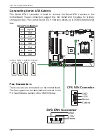
3. System Fan Connector
4. Serial-ATA (SATA) Connectors
5. Front Panel Header
6. Speaker Header
7
.
Clear CMOS Jumper
8. South Bridge
9. USB Headers
10. Floppy Disk Drive Connector
11. COM Port Header
12. PCI Slots
13. SPDIF-Out Header
14. Front Audio Header
15. PCI Express x16 Slot
16. Backpanel Connectors
17. 4-pin ATX_12V Power Connector
18. CPU Fan Connector
19. CPU Socket
20. North Bridge
21. DDRII DIMM Sockets
120
240
121
LO
TE
S
R
E
O
E
V
M
Li
th
iu
m
ce
ll
C
R2
03
2
3V
S
C
8
120
240
121
North Bridge
South Bridge
F Audio
_
PW2
SY
S_
FA
N
PW
1
SATA1
SPDIF
COM
FP1
SPK1
USB2
USB1
ID
E
JP
1
SATA2
SATA3
SATA4
FLOPPY
US
B
PCI2
PCI1
PCIE1
D
D
RII
1
KB
1
D
D
RII
2
CPU FAN
_
SD
1
D
VI
VG
A
US
B
LA
N
_
12
2
3
4
5
6
7
8
9
10
11
13
14
15
16
17
18
19
20
21
Summary of Contents for G41 series
Page 41: ...41 3 Follow the below for Intel graphics drive Installing Installing Drivers and Software ...
Page 42: ...42 Intel G41 Chipset Motherboard ...
Page 43: ...43 Installing Drivers and Software ...
Page 44: ...44 Intel G41 Chipset Motherboard 4 Follow the below for HDA sound driver installing ...


