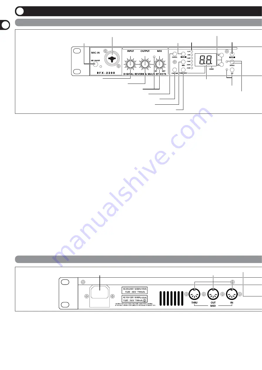
Zoom RFX-2200 Operation Manual Download Page 2

Contr

ols

and

Functions

(1) MIC IN connector 

A microphone with an impedance of about 600 ohms can
be connected here, for use as an additional input source.
Either an XLR plug (balanced connection) or a phone
plug (balanced/unbalanced connection) can be used. 
Normally the input signal from this connector is mixed
with the signal from the rear-panel INPUT jacks. When
the VOCODER effect is selected, the signal from this
connector serves for controlling the sound character and
the envelope (volume change curve) of the VOCODER
effect. 

(2) MIC ON/OFF switch 

This switch turns the signal from the MIC IN connector
on and off. When the switch is ON, the indicator at the
right lights up. 

(3) INPUT control 

Serves to adjust the signal from the INPUT jacks and the
MIC IN jack. 

(4) OUTPUT control 

Serves to adjust the level of the signal supplied at the
OUTPUT jacks. 

(5) MIX control and LED 

Serves to adjust the balance between original sound
(DRY) and effect sound (WET). When the control is
turned fully counterclockwise, only the original sound is
output. When the control is turned fully clockwise, only
the effect sound is output. If the mixing balance setting
was changed since the last store operation, the LED lights
up. 

(6) CANCEL key 

Serves to cancel a store operation. 

(7) COMPARE key 

When a patch (group of stored effect settings) is being
edited, this key can be used to compare the sound before
and after the edit. 

(8) MIDI key 

This key is used to make various MIDI settings. 

(9) PARM CHECK key 

Serves for checking effect parameter settings. 

(10) STORE key 

Used for storing patches in memory and other functions. 

Front Panel

Rear Panel

(1)  MIC IN connector 

(2) MIC ON/OFF switch

(3)  INPUT control 

(4)  OUTPUT control 

(5)  MIX control and LED  

(6)  CANCEL key 

(7)  COMPARE key 

(8)  MIDI key 

(9)  PARM CHECK key 

(10)  STORE key  (11)  Level meter 

(12)  VALUE UP/DOWN keys 

(13)  BANK key 

(14)  Display 

(15)  TAP key and LED 

(16)  BYPASS key and LED 

(2)  MIDI connectors 

(3)  BYPASS jack 

(1) POWER connector 

(1) POWER connector 

The supplied power cord is to be connected here for
powering the unit. 

(2) MIDI connectors 

Serve for connection to the MIDI interface of a computer
or to a MIDI keyboard or similar. This allows patch
switching from external equipment. 

(3) BYPASS jack 

Serves for connection of the foot switch FS01 (option) for
switching effects on and off. 

(4) DIGITAL OUT connectors 

The same signal as available at the OUTPUT jacks is
carried by these connectors in S/PDIF digital format. This
can be used to supply the signal to consumer equipment

Controls and Functions 

2

ZOOM RFX-2200

Summary of Contents for RFX-2200

Page 1: ...ing the VOCODER effect is a snap thanks to this feature Built in tap input Time based parameters such as delay time can be entered directly using the tap input feature This makes it easy for example t...

Page 2: ...nce the last store operation the LED lights up 6 CANCEL key Serves to cancel a store operation 7 COMPARE key When a patch group of stored effect settings is being edited this key can be used to compar...

Page 3: ...sound is output In this condition the LED is lit 17 BANK LEDs These indicators show which bank is currently selected 18 EFFECT TYPE selector and LED Serves to choose an effect from the currently sele...

Page 4: ...made in the digital domain In this configuration the MIX control of the RFX 2200 should be set so that it outputs only the effect sound and the balance between original sound and effect sound should b...

Page 5: ...recorded voice RFX 2200 This is a connection example for using the VOCODER effect from the SFX bank Plug a mic into the front panel MIC IN connector and connect a synthesizer or other instrument to t...

Page 6: ...2 Turn on the system in the following order sound source RFX 2200 playback system 3 While playing the sound source turn up the INPUT control of the RFX 2200 to adjust the input level To minimize noise...

Page 7: ...o the original effect the LED goes out When calling up a patch the LED of the bank where the patch is stored lights up BANK key Bank switching BANK key Bank switching REVERB or SFX bank selected DELAY...

Page 8: ...meter Checking the parameter value parameter check 1 Select the patch and edit it 2 Press the STORE key The patch number on the display flashes 3 Use the VALUE UP DOWN keys to select the patch number...

Page 9: ...g any of the controls in compare mode has no effect Shown alternately COMPARE key Setting Parameters With the Tap Key Tap Input 1 Select a patch for which tap input is possible Whether tap input is po...

Page 10: ...nt to assign a program change number and press the MIDI key two times The indication PC and the indication are shown alternately on the display 2 Send a program change message from the MIDI device con...

Page 11: ...message at the start of the sequencer track which calls the patch to be used as operation start point 2 Start the MIDI sequencer and start recording 3 Operate the control knobs on the front panel of t...

Page 12: ...ess the STORE key The sending RFX 2200 starts to transmit the data The data are received automatically by the receiving RFX 2200 No special steps are necessary During the transfer the indication dt fl...

Page 13: ...data and learn table data in the memory of the receiving RFX 2200 are overwritten The indication dr flashes on the display while data are being received When current patch number was selected for sen...

Page 14: ...djusts the reverb time Adjusts EQ Low boost cut Adjusts EQ High boost cut Selects the reverb character see table S R S R S R S R S R S R S R S R This bank contains only reverb effects The parameters R...

Page 15: ...e for strings 10 Choral Mix Rich ambience for chorus and vocal ensembles 11 Percussion Mix Ambience suitable for percussion ensembles 6 PERCUSSION 1 Rock Kit 1 Reverb suitable for rock drum 2 LatinPer...

Page 16: ...ing cycle Adjusts the delay time in 1 ms units Adjusts the amount of feedback Negative values result in cross feedback Adjusts the delay time in 1 ms units Adjusts the amount of feedback Adjusts the d...

Page 17: ...Parameter Setting range Description Adjusts the depth of the effect Adjusts the modulation cycle Adjusts the amount of feedback Selects the number of phaser stages and the phase 1 5 4 6 8 10 normal p...

Page 18: ...ratio Control knob Parameter Setting range Description Adjusts the reverb duration Adjusts the flanger fluctuation cycle Adjusts the flanger feedback Adjusts the reverb mix ratio S R S R S R 1 VOCODE...

Page 19: ...rtion S R S R 7 GATE REV GATE REVERB Special effect where the reverb is briskly cut by a gate EDIT 1 EDIT 2 EDIT 3 EDIT 4 TAP BYPASS Threshold Reverb Time EQ Low EQ High WET MUTE 1 11 1 30 12 12 12 12...

Page 20: ...8 HPF HIGH PASS FILTER This is a filter which lets only high frequency signal components through EDIT 1 EDIT 2 EDIT 3 EDIT 4 TAP BYPASS Resonance Frequency LFO Rate TAP LFO Depth WET MUTE 1 11 1 30 1...

Page 21: ...2 EDIT 3 EDIT 4 TAP BYPASS Reverb Character Reverb Time Reverb Mix Intensity 1 11 1 30 0 99 0 15 Control knob Parameter Setting range Description Control knob Parameter Setting range Description Contr...

Page 22: ...usts EQ Low boost cut Adjusts EQ High boost cut Selects the microphone character and the degree of enhancement 1 6 For vocals 7 11 For instruments larger values result in stronger enhancement Control...

Page 23: ...no Verb String Texture Church Organ Large hall reverb for ensembles Short bright reverb for drums Rich long reverb for chant 132 BPM dotted 8th note delay 200 ms auto panning delay Delay reverb good o...

Page 24: ...Sim w enhance Detailed Near Fields Detailed Room Monitors Reverb for snare drum Adds vitality to kick drums Makes crunch guitar sound fatter Short thick reverb for voice Good with melodic solo instrum...

Page 25: ...ar panel INPUT jack Connect the microphone to the front panel MIC IN jack Is unit in bypass mode and is MIX control fully turned to the WET position Turn MIX control towards DRY Is EDIT control knob 1...

Page 26: ...ocity Note ON x x Note OFF x x After Key s x x Touch Ch s x x Pitch Bend x x 86 86 Effect Type 84 84 Edit1 Control Change 85 85 Edit2 87 87 Edit3 88 88 Edit4 8 8 Mix 80 80 91 Bypass 64 64 Tap Prog o 0...

Page 27: ...and input and output jacks You should always turn off the power to the RFX 2200 and all other equipment before connecting or disconnecting any cables Also make sure to disconnect all connection cables...

Page 28: ...ZOOM CORPORATION ITOHPIA Iwamotocho 2chome Bldg 2F 2 11 2 Iwamoto cho Chiyoda ku Tokyo 101 0032 Japan Web Site http www zoom co jp RFX 2200 5000 2...

Reviews: