Zoeller 64 HD Series Owner'S Manual Download Page 4

4

© Copyright 2017 Zoeller

®

 Co. All rights reserved.

All installations must comply with all applicable electrical and plumbing codes, including, but not limited to, National Electrical Code, 

local, regional, and/or state plumbing codes, etc.

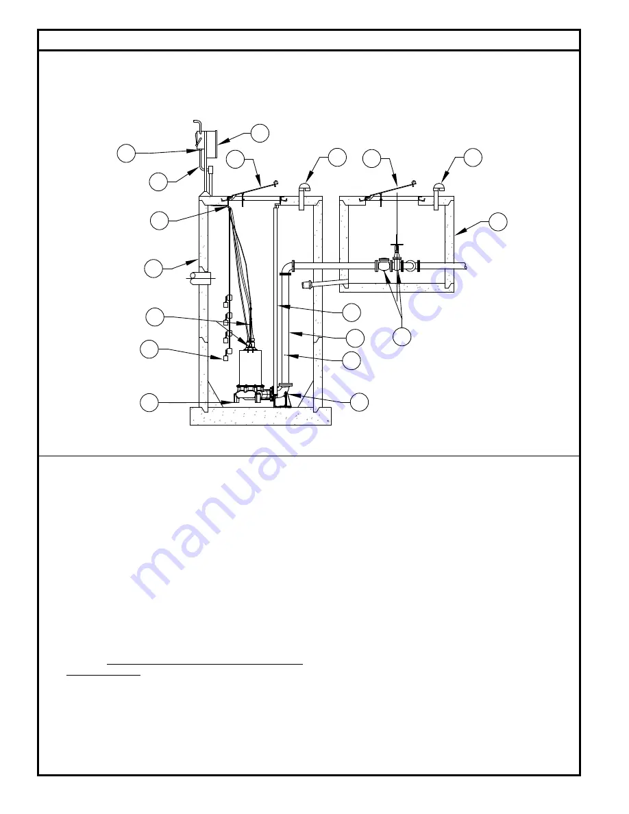
TYPICAL OUTDOOR CONCRETE BASIN WITH VALVE BOX AND HINGED ACCESS COVERS

Typical Sewage/Waste Pumping System Installation

  (1)   Electrical wiring and protection 

must 

be in accordance with the 

National Electrical Code, and any other applicable state and local 

electrical requirements.

  (2)   Install proper full flow check and shut-off valve.

  (3)   Install proper controls. (Outdoor panels 

require 

NEMA 3R or 4X 

enclosure)

  (4)   All installations 

require 

a basin cover to prevent debris from falling 

into the basin and to prevent accidental injury.

  (5)   Gas tight seals are 

required in all indoor sewage installations


to contain gases and odors.

  (6)  

When check valve is installed, drill a 3/16” diameter hole in 

the discharge pipe below the check valve even with the top of 

the pump. NOTE: The hole must be below the basin cover and 

cleaned periodically. Water stream will be visible from this hole 

during pump run periods. Also a vent hole is drilled in the pump 

housing. Be sure that this hole is cleared during any servicing.

  (7)   Vent gases and odors to the atmosphere through vent pipe per 

Local and State codes.

  (8)   Secure power cord to avoid entanglement with variable level float 

switch mechanism.

  (9)  

Do not reduce pump discharge pipe below 4” IPS size.

  (10)   Basin 

must 

be in accordance with all applicable codes


  and specifications. Basin must be sized to allow a minimum 3 

minute lapse time between starts.

  (11)   Pump must be level and the tethered variable level float switch 

must be free and not hang up on pump or pit peculiarities.

 (12) 

If

 a rail system is used, discharge elbow 

must be firmly anchored 

to the bottom of basin. In fiberglass basin, the bottom will need 

to be reinforced if the discharge elbow is used.

 (13) 

If a rail system is used, the guide rails are 2” schedule 40 pipe 

for flanged horizontal discharge units. Brass, stainless steel or 

galvanized steel is recommended.

  (14)   Install ring and cable for lifting pump from pit.

  (15)   Basin must be clean and free of debris after installation.

  (16)  Cords must be properly sealed to prevent moisture and gases 

from entering the control panel. 

ZEPA0071_6680

9

10

16

1

8

4

3

4

7

10

7

15

14

11

12

13

2

6

Summary of Contents for 64 HD Series

Page 1: ...tion Reference ZM3013 for repair manual on 64 HD Series Pumps Should further assistance be necessary please call our Product Support Department at 1 800 928 PUMP 7867 Table of Contents Safety Instructions 1 Limited Warranty 2 Preinstallation Information 3 Electrical Data 3 Typical Sewage Installation 4 Pump Wiring Instructions 5 6 Operation 7 Maintenance 7 Service Checklist 8 Safety Instructions T...

Page 2: ...ngineered Products or an authorized service facility and found to be defective by the company Part s that fail and that inspection determines to be defectiveinmaterialorworkmanship willberepaired replaced orremanufacturedat Zoeller Engineered Product s option provided however that by so doing we shall not be obligated to replace an entire assembly the entire mechanism or the complete unit Major co...

Page 3: ...damaged during shipment If the unit is damaged contact your dealer before using DO NOT remove the test plugs in the cover nor the motor housing 2 Carefully read the literature provided to familiarize yourself with specific details regarding installation and use These materials should be retained for future reference 1 Do not lift carry or hang pump by the electrical cables Damage to the electrical...

Page 4: ...ll be visible from this hole during pump run periods Also a vent hole is drilled in the pump housing Be sure that this hole is cleared during any servicing 7 Vent gases and odors to the atmosphere through vent pipe per Local and State codes 8 Secure power cord to avoid entanglement with variable level float switch mechanism 9 Do not reduce pump discharge pipe below 4 IPS size 10 Basin must be in a...

Page 5: ...isture detection circuit An indicator light will activate when ever water is present in the shaft seal cavity or cord cap assembly Whenever the seal leak light is activated indicating the entry of moisture into the pump it should be removed and serviced in order to avoid damage to the motor Moisture sensor circuit can be checked for continuity complete circuit with a Volt OHM Meter Set the VOM to ...

Page 6: ...ination locations NOTE Sensor cable includes 5 leads 2 leads for thermal sensor 2 leads for moisture sensor and a green ground lead Sensor wire colors are as shown N C SENSOR 330K OHMS RESISTANCE SEAL FAILURE PROBES PANEL INDUCTION CIRCUIT IN THE CONTROL LEADS MUST BE CONNECTED TO SEAL FAILURE MOISTURE SENSOR STARTER COIL CONNECTED IN SERIES WITH RECOMMENDED THERMAL SENSOR THERMAL T3 T2 T1 L3 L2 L...

Page 7: ...temisshutdownformorethansixmonths thefollowingisrecommended Pumps If pit is to remain dry then the pump can remain in the pit With the pump in the pit it should be operated for five minutes once every threemonths Ifthepitistoremainwet thepumpshouldberemoved and stored as noted above Panels Thepanelshouldhaveallopeningssealedtopreventmoistureanddust fromenteringtheenclosure Priortorestartingsystem ...

Page 8: ...adjustment or defective Pit too small D Pump will not shut off Debris under float switch Float travel obstructed Defective or damaged float switch Magnetic starter contacts shorted Air lock check vent hole E Pump operates but delivers little or no water Check for plugged Pump housing discharge pipe or sticking check valve Vent hole clogged or not drilled Discharge head exceeds pumps capacity Low o...

Reviews: