background image

17

• 

In addition to conventional charging procedures, the following requirements apply.


- Check that there is no possibility of cross-contamination between the different refrigerants when using charging 

equipment. Hoses or lines must be as short as possible to reduce the quantity of refrigerant contained therein.


- Cylinders must be kept in an appropriate position, in accordance with the instructions.


- Check that the cooling system is grounded before charging the system with refrigerant.


- Label the system once charging is complete (if this is not already the case).


- Pay close attention to not overfilling the cooling system.

• 

Before recharging the system, carry out a pressure test using a suitable purge gas. The system must be examined to 

make sure there are no leaks after the charging operation and before commissioning. A follow-up leak test must be 

carried out before leaving the site.

Dismantling

• 

Before dismantling, the technician must familiarise himself/herself with the equipment and its specifications. We 

highly  recommend  carefully  recovering  all  refrigerants.  Before  this,  oil  and  refrigerant  samples  must  be  taken  if 

analyses are to be carried out before any other use of the recovered refrigerant. Check for the presence of a power 

supply before starting work.

1. Familiarise yourself with the equipment and how it operates.

2. Electrically isolate the system.

3. Before starting work, check the following points:


- mechanical handling equipment is available if needed to handle the refrigerant cylinders;


- all personal protective equipment is available and used correctly;


- the recovery process is monitored at all times by a cognisant person;


- the recovery cylinders and equipment comply with the relevant standards.

4. Drain the cooling system where possible.

5. If a vacuum cannot be created, install a manifold in order to be able to remove the refrigerant from various locations 

within the system.

6. Make sure that the cylinder is located on the scales before starting recovery operations.

7. Start the recovery unit and operate as per its instructions.

8. Do not overfill the cylinders (no more than 80% of the volume must be filled with liquid).

9. Do not exceed the maximum working pressure of the cylinder, even temporarily.

10. When  the  cylinders  have  been  filled  correctly  and  the  process  is  complete,  check  that  the  cylinders  and  the 

equipment are quickly removed from the site and that the alternative shut-off valves on the equipment are closed.

11. The recovered refrigerant must not be charged in another cooling system, unless it has been cleaned and inspected.

4.2.2 User maintenance

• 

Make sure that the filter is not blocked by any foreign bodies.

• 

Clean the evaporator (for location see § “1.3 I  Dimensions and marking”) using a soft brush and a fresh water spray 

(disconnect the power cable); do not fold over the metal wings, then clean the condensation drainage pipe to remove 

any impurities that may be blocking it.

• 

Do not use a high pressure jet. Do not spray with rain water, salt water or water which is full of minerals.

• 

Clean the outside of the device; do not use any solvent-based products. We can provide you with a specific cleaning 

kit as an accessory: the PAC NET, see § “1.1 I  Description”.

4.2.3 Maintenance to be carried out by a qualified technician

• 

Please read the safety instructions provided in the chapter entitled  «4.2.1 Safety instructions 

for  appliances  containing  R32  refrigerant»  before  performing  any  of  the  maintenance 

operations described below.

• 

Check that the regulation is operating correctly connected.

• 

Check that the condensation flows correctly when the device is operating.

• 

Check the safety mechanisms.

• 

Check the connection of the metal masses to the earth.

• 

Check that the electrical cables are correctly tightened and connected and that the electrical unit is clean.

EN

Summary of Contents for Z200

Page 1: ...H0548500_REVF 2021 02 More documents on www zodiac com Z200 Defrost Z200 PI20 Defrost PI20 Instructions for installation and use English Heat pump Translation of the original instructions in French EN...

Page 2: ...sed for any purpose other than that for which it was designed This appliance is not intended for use by individuals including children with impaired physical sensorial or mental abilities or persons l...

Page 3: ...on the appliance with wet hands or if the appliance is wet Before connecting the appliance to the source of supply ensure that the terminal block or supply socket to which the appliance will be conne...

Page 4: ...designated for the recovered refrigerant and labelled for that refrigerant i e special cylinders for the recovery of refrigerant Cylinders shall be complete with pressure relief valve and associated s...

Page 5: ...rinciple 12 3 2 User interface presentation 12 3 3 I Operating 13 3 4 I User functions 14 Maintenance 15 4 1 I Winterizing 15 4 2 I Maintenance 15 Troubleshooting 18 5 1 I Device behaviour 18 5 2 I Er...

Page 6: ...A Z200 PI20 B Joint x2 C Screw in connector x2 D 40 adaptation x2 E 50 reduction x2 F Condensation evacuation kit 15 G Winterizing cap x2 H Winterizing cover Heating priority I Remote control J PAC N...

Page 7: ...cable section mm 3x2 5 3G2 5 Proof pressure bar 6 Service pressure bar 1 5 Max Discharge Suction Pressure bar 42 1 2 Max high pressure low pressure side pressure bar 42 1 2 Head loss mCE 1 1 5 1 1 5...

Page 8: ...on valve and user interface Ventilator Technical access door Pool water intake Pool water output Evaporator Grommet for heating priority cable run Location for drilling for remote control cable run de...

Page 9: ...und The device must not be installed In a closed and unventilated room In a location subject to high winds With the blowing towards a permanent or temporary obstacle window wall hedge awning etc less...

Page 10: ...o make it easier to work on the device water entry valve by pass valve water exit valve water entry adjustment valve optional water exit adjustment valve optional water treatment minimum distance To e...

Page 11: ...hnical specifications with a 30 mA dedicated differential circuit breaker circuit breaker or switch at the head of the line The electricity supply must correspond to the voltage indicated on the devic...

Page 12: ...p power contactor coil filtration timer power contactor tripolar or bipolar for the filtration system pump motor separate cable for the heating priority function heat pump terminal see wiring diagram...

Page 13: ...ing range sufficient to heat Cover the basin with a sheet bubble canopy canvas etc to prevent heat loss Take advantage of a period with mild outdoor temperatures on average 10 C at night your heat pum...

Page 14: ...adually so that the filter pressure is increased by 150g 0 150 bars Open valves A C and D fully then valve E by half the air which has built up in the heat pump condenser and the filtration circuit wi...

Page 15: ...the setpoint temperature is displayed fixed To read the water temperature it is imperative that the filtration is in operation and that the water flow indicator is fixed 3 4 2 Locking unlocking the k...

Page 16: ...nd other personnel working in the surrounding area must be made aware of the work carried out Work conducted in enclosed areas must be avoided Check for the presence of refrigerant The area must be an...

Page 17: ...nd intensity for the equipment being used Typically safe components are the only types on which work can be carried out in the presence of a flammable atmosphere when live The test appliance must fall...

Page 18: ...ll a manifold in order to be able to remove the refrigerant from various locations within the system 6 Make sure that the cylinder is located on the scales before starting recovery operations 7 Start...

Page 19: ...your heat pump cannot manage to deice its evaporator it will stop itself this means that the outdoor temperature is too low below 5 C for standard models 5 C for Defrost models The device is not worki...

Page 20: ...temperature too high 32 C maximum Wait until the temperature falls Flow controller blocked Check the flow controller Water condenser scaled up or blocked Clean the water condenser Outside temperature...

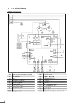
Page 21: ...p relay Earth KM4 Complementary relay C1 Compressor condenser M1 Compressor C2 Ventilator condenser M2 Ventilator CD Flow controller SD1 Water temperature sensor E1 High pressure switch SD2 Air temper...

Page 22: ...KM4 Complementary relay C1 Compressor condenser M1 Compressor C2 Ventilator condenser M2 Ventilator CD Flow controller SD1 Water temperature sensor HP High pressure switch SD2 Air temperature sensor...

Page 23: ...rty of their respective owners Votre revendeur Your retailer Mod le appareil Appliance model Num ro de s rie Serial number Pour plus d informations enregistrement produit et support client For more in...

Reviews: