Zmotion ZMC304X306X Hardware Manual Download Page 24

ZMC304X/306X Hardware Manual Version1.3 


20 


Chapter IV Common Problems 

Problems


Suggestions


Motor does not rotate.


Check whether the ATYPE of the controller is correct; 

Check  whether  the  pulse  input  mode  matches  the  input 

pulse mode of the drive; 

Check  whether  the  motor  already  reached  hardware  or 

software position limit, resulting in ALM signal comes. 

Check whether pulse count is normal in ZDEVELOP.


The  controller  is  working 

normally,  pulses  is  sent  out 

normally,  motor  still  does  not 

rotate.


Check  whether  connection  between  drive  and  motor  is 

correct  and  whether  connection  between  the  drive  and  the 

controller is correct. 

Check  whether  the  drive  works  properly  and  there  is  no 

alarm.


Motor  can  rotate,  but  it  is  not 

working normally.


Check  whether  deceleration  and  speed  exceed  the  device 

limit; 

Check whether pulse frequency output exceed the


receiving limit of the drive;


Check whether connection between controller and drive are 

correct  and  whether  anti-interference  measures  are  well 

done; 

Check  whether  current  limiting  resistance  used  in  the 

photoelectric  isolation  circuit  of  pulse  and  direction  signal 

output is too large and the working current is too


small.


Motor  is  under  control,  but  it 

may  oscillate  or  overturn 

sometimes.


Check whether the drive parameters setting is correct. 

Check  whether  acceleration  or  deceleration  period  and 

motion speed were set properly in Software.


Motor  is  under  control,  but 

homing position is inaccurate.


Check  whether  the  origin  signal  switch  is  working 

normally;


Check whether the origin signal is disturbed.


The  position  limit  signal  is 

invalid.


Check  whether  the  position  limit  sensor  is  not  working 

normally;


Check whether t

he signal of the limit sensor is disturbed;


The expansion module can not 

be  connected,  and  alarm  light 

of the expansion module is on.


Check whether there is a 120Ω resistor at both ends; 

Check whether multi expansion modules use the same ID.


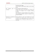
No signal comes to the input.


Check whether the IO is supplied normally; 

Check  whether  the  input  signal  level  matches  the  input 

channel. 

Check  whether  the input  number matches the  ID  of  the  IO 

board.


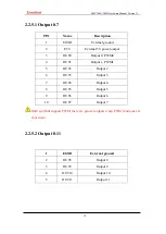
The output does not work.


Check whether the IO is supplied normally; 

Summary of Contents for ZMC304X306X

Page 1: ...ZMC304X306X Hardware Manual Version 1 3...

Page 2: ...e introduction and routines of each instruction please refer to ZBASIC software manual Information contained in this manual is only for reference Due to improvements in design and functions and other...

Page 3: ...2 2 Communication Interface 8 2 2 3 RS232 Interface 9 2 2 4 General Input 9 2 2 4 1 Input 0 7 10 2 3 4 2 Input 8 15 10 2 2 4 3 Input 16 23 11 2 2 5 General Output 11 2 2 5 1 Output 0 7 12 2 2 5 2 Outp...

Page 4: ...ZMC304X 306X Hardware Manual Version1 3 3 Chapter V Hardware Installation 22 5 1 ZMC304X 306X Installation Size 22...

Page 5: ...lectronic cam electronic gear synchronous following virtual axis etc Real time motion control can be realized through optimized network communication protocol One computer can link with up to 256 ZMC...

Page 6: ...ng compiling and debugging environment Communication between controller and ZDEVELOP can be built through serial port 485 USB or Ethernet Application can be developed in PC languages such as VC VB VS...

Page 7: ...nal of axis can be configured to any inputs The output current can reach 300mA which can directly drive some kinds of solenoid valves Interface USB Drive RS485 RS422 and ETHERNET etc Linear interpolat...

Page 8: ...1 output the output in the axis can only be enabled Maximum extended IO Up to 512 inputs and 512 outputs PWM 2 output frequency 1M Internal ADDA 2 ADs 2DAs 0 10V Max extended AD DA 256 ADs 128 DAs Pu...

Page 9: ...4 axes point to point interpolation of linear circular electronic cam continuous interpolation Robotics instruction ZMC304X 1 4 axes point to point electronic cam ZMC304X 2 4 axes point to point inte...

Page 10: ...l axis Axes can be extended through extension modules There are 24 general inputs and 12 general outputs in ZMC306X each axis has another 1 input and 1 output 2 ADs 0 10V and 2 DAs 0 10V 1 RS232 1 RS4...

Page 11: ...Power 24V input 2 EGND External Ground 3 FG EARTH Shield ZMC306X series controller uses single power ZMC0 2 series and ZIO expansion modules use double power controller 5V pulse axes and encoder inte...

Page 12: ...AN bus it is necessary to connect 120 resistor between CANL and CANH of the last IO expansion module Communication interfaces on ZMC3XX series controllers usually use external 24V power Be careful whe...

Page 13: ...Name Description 2 RXD Receive data PIN 3 TXD Send data PIN 5 EGND Power source 9 E5V External 5v output it supplies text screen Crossover cable with two female head is needed when try to link to comp...

Page 14: ...ch B 5 IN2 Input 2 6 IN3 Input 3 7 IN4 Input 4 8 IN5 Input 5 9 IN6 Input 6 10 IN7 Input 7 Input o and input 1 both support latch A and latch B synchronously 2 3 4 2 Input 8 15 PIN Name Description Def...

Page 15: ...round 2 EGND External ground 3 IN16 Input 16 4 IN17 Input 17 5 IN18 Input 18 6 IN19 Input 19 7 IN20 Input 20 8 IN21 Input 21 9 IN22 Input 22 10 IN23 Input 23 2 2 5 General Output Output Circuit There...

Page 16: ...t 3 OUT0 Output 0 PWM0 4 OUT1 Output 1 PWM1 5 OUT2 Output 2 6 OUT3 Output 3 7 OUT4 Output 4 8 OUT5 Output 5 9 OUT6 Output 6 10 OUT7 Output 7 Out0 and Out1support PWM there are general outputs when PWM...

Page 17: ...AIN0 0 10V Analog input 0 5 AIN1 0 10V Analog input 1 Inside ZMC306X uses internal power supply 2 2 7 USB Drive PIN Name Description 1 V USB 5V power output 2 D Differential data D 3 D Differential d...

Page 18: ...EZ Encoder input 7 5V Internal 5V Power output 8 Reserved Reserved 9 DIR Direction of servo or stepper output 10 GND Digital ground 11 PUL Servo or stepper pulse output 12 Reserved Reserved 13 GND Dig...

Page 19: ...ion1 3 15 23 PUL Servo or stepping pulse output 24 GND Digital Ground 25 Reserved Reserved 26 Reserved Reserved 2 2 8 1 Wiring Reference for Low speed Differential Pulse or Encoder Axis Differential C...

Page 20: ...ZMC304X 306X Hardware Manual Version1 3 16 Encoder Connection Low speed differential pulse wiring reference between ZMC306X and Panasonic A5 servo drive...

Page 21: ...together 2 2 8 2 Wiring Reference for High speed Differential Pulse or Encoder Axis If the low speed differential pulse meets the speed requirement using low speed differential pulse preferentially Or...

Page 22: ...ZMC304X 306X Hardware Manual Version1 3 18 High speed differential pulse wiring reference between ZMC306X and Panasonic A5 servo drive...

Page 23: ...ies controller uses single power ZIO expansion module card uses double power to supply in actual application ZIO power channels on expansion modules can share the same power supply When ZMC306X series...

Page 24: ...well done Check whether current limiting resistance used in the photoelectric isolation circuit of pulse and direction signal output is too large and the working current is too small Motor is under co...

Page 25: ...lt between controller and computer but computer does not support automatic crossing Check whether the controller IP address has been modified Check whether the IP address segment of computer is same a...

Page 26: ...ZMC304X 306X Hardware Manual Version1 3 22 Chapter V Hardware Installation 5 1 ZMC304X 306X Installation Size Unit mm mounting hole diameter 4 5mm...

Reviews: