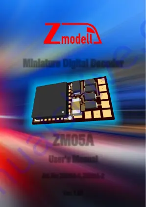
Miniature Digital Decoder
ZM05A
User’s Manual
Art. No: ZM05A-1, ZM05A-2
Ver. 1.07
Page 1: ...Miniature Digital Decoder ZM05A User s Manual Art No ZM05A 1 ZM05A 2 Ver 1 07...
Page 2: ...Introduction Top Side Bottom Side Variant with connection wires M1 M2 G1 G2 GND AUX4 AUX3 LV LV VS AUX2 AUX1 LR LV M1 M2 G1 G2 GND LV LR AUX1 AUX2 VS AUX4 AUX3...
Page 3: ...onnection 1 2 LV Front light 150 mA max LR Rear light 150 mA max AUX1 AUX2 Additional functions 1 2 300 mA max AUX3 AUX4 Additional functions 3 4 unamplified 5V 20 mA max VS Supply voltage GND Ground...
Page 4: ...e digital decoder 3 Disconnect the motor and all lights of the locomotive from the tracks and make sure that both outputs of all these consumers are fully isolated from the track connections It is als...
Page 5: ...e locomotive is equipped with separately controlled white headlights and red tail lights This is the most advanced variant of controlling light functions of the locomotive It allows independent switch...
Page 6: ...dinthiscase 6 Using AUX3 and AUX4 outputs these outputs are non amplified and cannot switch high current loads They provide maximal output voltage of 5 V regardless of the track voltage Please note th...
Page 7: ...voltage 20 25 depending on the track voltage For example it is recommended to use capacitors rated for 16 V if the track voltage is 12 V If the track voltage is 16 V usecapacitorsratedfor25V andsoon I...
Page 8: ...ad out the locomotive address Program the desired locomotive address and start running the locomotive After the first check you can modify the driving parametersaccordingtoyourrequirements In case you...
Page 9: ...top 0 255 3 05 Maximum speed 0 127 92 08 Decoder reset Write 8 to this CV in order to reset the digital decoder to default settings 13 Activation F1 F8 in analog mode Bit Function Value Bit Function V...
Page 10: ...ion Range Default 51 Swapping connections Bit Function Value 0 Motor swapping M1 and M2 outputs 1 1 Light swapping LV and LR outputs 2 2 Track swapping G1 and G2 outputs 4 0 7 0 52 Dimming LV LR outpu...
Page 11: ...ports 14 28 and 126 speed steps In case the speed steps programmed on the decoder differ from those of the control device malfunctionsmayoccur This decoder supports braking with asymmetric digital vol...
Page 12: ...or disassembly of the model as well as by exceeding the maximumallowedoperatingparameters IMPORTANT Soldering work required for installation of this decoder Solderingironwiththintip 1mm andgoodsolderi...