background image


ZK55 Series User Manual


14 

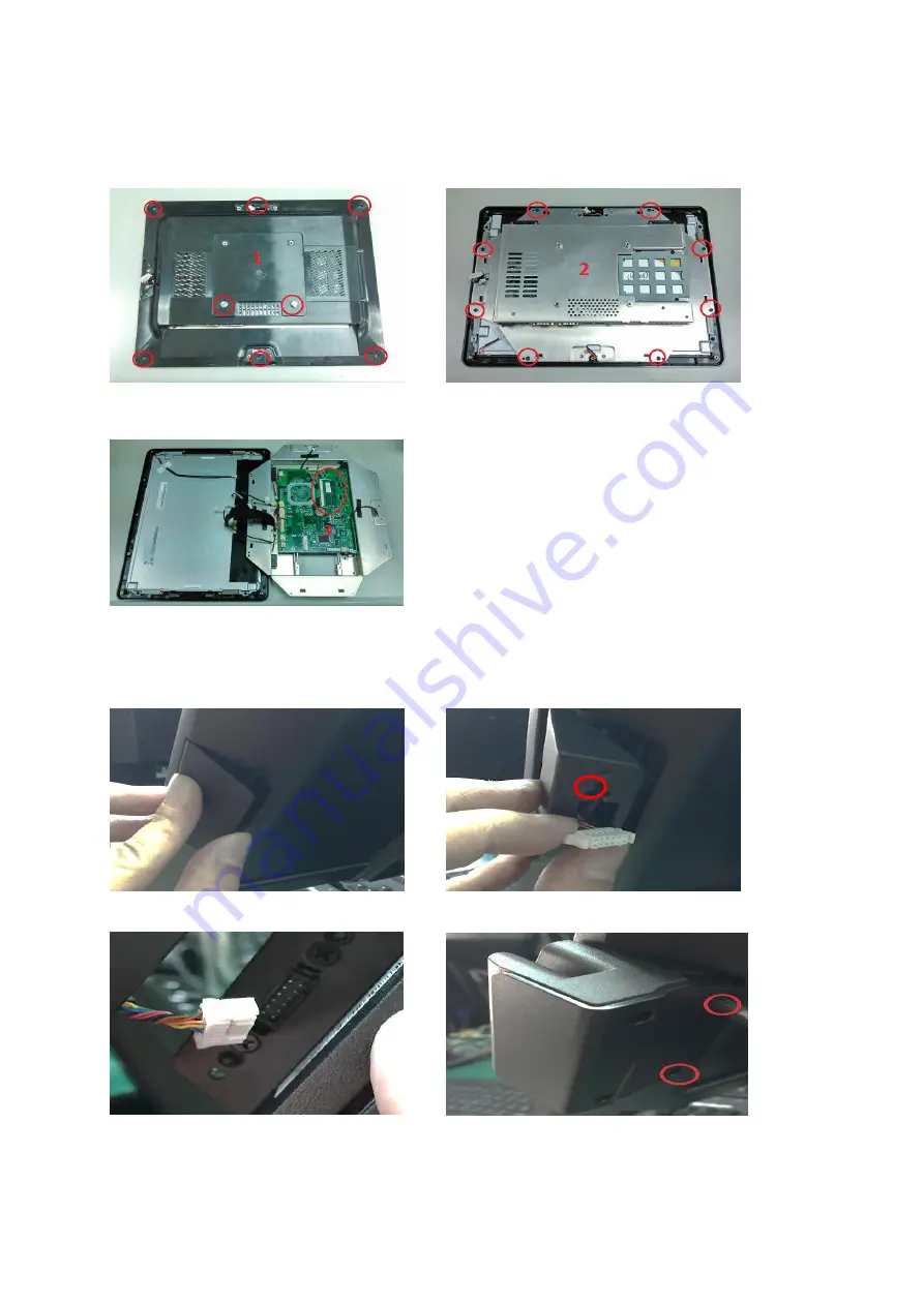
5.2. Memory 


1. Dis-fasten 8 screws and remove back cover.          2. Dis-fasten chassis 8 screws. 


5.3. MSR / i-Button / RFID 


1. Remove MSR cover.                                                2. Fasten the MSR holder with 2 screws. 


3. Plug the MSR cable into the MSR connector.        4. Reinstall the MSR cover with 2 screws. 

3.      Insert the RAM into the RAM slot.   


Summary of Contents for ZK55 Series

Page 1: ...USER MANUAL ZK55 Series Version 1 0 Date April 2017...

Page 2: ...t allowed to excerpt copy the content of this manual in part or in full also spread in any form The product described in the manual maybe includes the software which copyrights are shared by the lice...

Page 3: ...ced in any form or by any means without the prior written permission from ZKTeco Due to the constant renewal of products the company cannot undertake the actual product in consistence with the informa...

Page 4: ...electrical shock 9 If one of the following situations arises get the equipment checked by a service personnel 10 The power cord or plug is damaged 11 Liquid has penetrated into the equipment 12 The eq...

Page 5: ...ion 9 3 9 Projected capacitive touch connector Pin Definition 9 3 10 Resistive touch connector Pin Definition 9 3 11 COM3 connector Pin Definition 10 3 12 Sideward MSR connector Pin Definition 10 3 13...

Page 6: ...Card Reader Configuration Utility 22 6 3 RFID 27 6 4 Configuration Utility of i Button Reader Installation 32 6 5 VFD 35 7 BIOS Utility setup 40 7 1 Advanced 41 7 1 1 Boot Configuration 42 7 1 2 Audio...

Page 7: ......

Page 8: ...ZK55 Series User Manual 1 1 Packing List 1 1 Standard Accessories a b a System with stand b Power Adapter c Power Cord d Driver Bank c d 1 2 Optional Accessories a b c...

Page 9: ...ZK55 Series User Manual 2 d e f g a Single MSR b VFD c 8 or 10 4 2nd Display d 1D or 2D Attached Type Barcode Scanner e 1D or 2D Handheld Type Barcode Scanner f Thermal Printer g Cash Drawer...

Page 10: ...ies User Manual 3 2 System View 2 1 Rear View 2 2 Back View Please make sure 19V DC plug in the right direction before plugging in DC jack VFD Cover 8 2nd 10 2nd optional MSR i Button RFID optional HD...

Page 11: ...pins powered COM with DC 5V 12V selection Cash Drawer Port X 1 12V 24V RJ11 cash drawer port Audio Port x 1 Line out Network LAN X 1 RJ45 10 100 1000 Base T Peripherals VFD 8 10 4 Attached second disp...

Page 12: ...ZK55 Series User Manual 5 2 4 Internal Layout M B PCBA R Touch P Touch LVDS VFD LED BKLT Speaker COM3 USB 2 0 MSR i Button RFID DDR3L SO DIMM Mini PCIe Power Button...

Page 13: ...finition No Definition No Definition 1 6 bit 8 bit selection 2 GND 3 DATA3 4 DATA3 5 GND 6 CLK 7 CLK 8 GND 9 DATA2 10 DATA2 11 GND 12 DATA1 13 DATA1 14 GND 15 DATA0 16 DATA0 17 GND 18 GND 19 3 3V 20 3...

Page 14: ...D 4 DTR 5 GND 6 DSR 7 RTS 8 CTS 9 5V 12V Ring 3 4 SATA 22 pin SATA Pin Definition No Definition No Definition S1 GND P1 N C S2 SATA_TX0_P P2 N C S3 SATA_TX0_N P3 N C S4 GND P4 GND S5 SATA_RX0_N P5 GND...

Page 15: ...ND 8 N C 36 USB D 9 GND 37 N C 10 N C 38 USB D 11 CLK_PCIE_N 39 N C 12 N C 40 GND 13 CLK_PCIE_P 41 N C 14 N C 42 N C 15 GND 43 N C 16 N C 44 N C 17 N C 45 N C 18 GND 46 N C 19 N C 47 N C 20 W_DISABLE...

Page 16: ...ition 1 5V Standby 2 5V Status 3 Power On 4 GND 3 8 1D 2D scanner connector Pin Definition No Definition 1 5V 2 USB D 3 USB D 4 GND 3 9 Projected capacitive touch connector Pin Definition No Definitio...

Page 17: ...RxD 3 TxD 4 DTR 5 GND 6 DSR 7 RTS 8 CTS 9 5V 12V Ring 10 GND 3 12 Sideward MSR connector Pin Definition No Definition 1 5V 2 USB D 3 USB D 4 GND 5 5V 6 USB D 7 USB D 8 GND 3 13 RJ11 Cash Drawer connec...

Page 18: ...DTR 7 5V 8 USB D 9 USB D 10 GND 4 Rear I O Interface 4 1 2 Layer USB2 0 connector Pin Definition No Definition No Definition 1 5V 5 5v 2 D 6 D 3 D 7 D 4 GND 8 GND 4 2 2 Layer USB3 0 2 0 connector Pin...

Page 19: ...anual 12 4 3 LAN RJ45 Pin Definition No Definition 1 MDI0A 2 MDI0A 3 MDI1A 4 MDI1A 5 MDI2A 6 MDI2A 7 MDI3A 8 MDI3A 4 4 LINE OUT JACK Pin Definition No Definition 1 GND_AUD 2 GND_AUD 3 LINE_OUTR2 4 LIN...

Page 20: ...User Manual 13 5 System Assembly Disassembly 5 1 HDD 1 Dis fasten 2 screws and remove base cover 2 Dis fasten 2 screws and remove base cover 3 Pull out HDD bracket 4 Insert the HDD and fasten 4 HDD br...

Page 21: ...rews and remove back cover 2 Dis fasten chassis 8 screws 5 3 MSR i Button RFID 1 Remove MSR cover 2 Fasten the MSR holder with 2 screws 3 Plug the MSR cable into the MSR connector 4 Reinstall the MSR...

Page 22: ...D cable into the VFD connector or plug the 8 or 10 2nd display cable into the 2nd display s connector Note display connector can only be connected to one device at a time 5 5 Thermal printer 1 USB Cab...

Page 23: ...printer 2 Plug the Type A end of a USB cable into the USB port on the POS system 3 Connect AC power cord to power DC power cord to printer 5 6 1D 2D Barcode scanner 5 6 1 1D 2D Attached Type Barcode...

Page 24: ...Manual 17 barcode connector 3 Install the barcode scanner with 2 screws 5 6 2 1D 2D Handheld Type Barcode scanner 1 Plug the barcode scanner into a USB port 5 7 Cash Drawer 1 Plug the RJ11 cable into...

Page 25: ...ZK55 Series User Manual 18 6 Device Driver Installation 6 1 Resistive Type Touch Panel and P CAP 1 Click Next 2 Click Next 3 Click Next 4 Select None Click Next...

Page 26: ...ZK55 Series User Manual 19 5 Click OK...

Page 27: ...ZK55 Series User Manual 20 6 Select Support Multi Monitor System Click Next 7 Click Next 8 Click Next 9 Click Next 10 Select Create a Galax Touch Utility shortcut on desktop Click Next...

Page 28: ...ZK55 Series User Manual 21 11 Would you do 4 point calibration now Click Yes 12 Do 4 points aligrment to match display 13 Calibration utility...

Page 29: ...device has its own Device ID e g DID 0x030F for keyboard and HID USB DID 0x5082 for keyboard HID and VCP USB 2 Utility Features After success device connection each supported command will get its resp...

Page 30: ...ion file from storage Save To File Save the current screen setting to file in storage Get Configuration Word Get current setting in the device connected Set Configuartion Word Set current setting on t...

Page 31: ...User Manual 24 iButton function areas 2 3 5 7 10 11 14 RFID function areas 2 4 5 8 11 15 Chip card function areas 16 Configure word detail Area 1 Track 1 JIS II Enable If enabled the track 1 data wil...

Page 32: ...r F will response when track data read fail Track Sentinel Enable Replaceable If enabled the reader will send start and end sentinel at begin and last position of each track data If replaceable these...

Page 33: ...card removed Area 9 Tracks Sequence Request Select the order of three tracks data returned Area 10 iButton ID Range Request Define the ibutton data range returned Area 11 Language Option Select one of...

Page 34: ...eturned Each Head Tail accepts10 bytes max long Invisible code Enter keyboard control code Area 15 RFID Response Port Select RFID ID response port right after tag attached or removed Head Tail Message...

Page 35: ...ZK55 Series User Manual 28 2 Double click to Update driver 3 Select Browse my computer for driver software 4 Click Browse to select file called HFF320U Driver FTD x64 and click Next...

Page 36: ...ZK55 Series User Manual 29 5 Install the driver 6 Install complete and then click close 7 Restart the computer...

Page 37: ...ZK55 Series User Manual 30 6 3 2 Install framework 4 0 1 Double click to install 2 Select I have read and accept the license terms And click Install...

Page 38: ...The demonstration software is MP Studio exe provided in the folder Demo Software There is no software setup required just double click the MP Studio exe The demonstration software can run either from...

Page 39: ...quick understanding 6 4 Configuration Utility of i Button Reader Installation Below steps guide you how to install the Utility program Insert the setup CD Run the ZKTeco IButton Utility exe setup file...

Page 40: ...ZK55 Series User Manual 33...

Page 41: ...module The utility program will detect the connected reader If detected all the input text boxes will be enabled If the reader has not been connected to PC yet please connect the reader and then clic...

Page 42: ...el byte for the i Button ID string i Button data format SS i Button 64 Bit Registration Number ES 1 Length i Button ID length request from 0 16 2 Output order 4 formats could be select at Attach Remov...

Page 43: ...as shown in the above figure the baud rate will show on states page of VFD module Note You may check it when power on VFD module then click Open COM button 4 Get Setting from VFD button to get all th...

Page 44: ...haracter Type USA Command Type EPSON EURPOPE Baud Rate Setting 9600 n 8 1 Pass through Mode None Welcome msg line1 VFD DISPLAY Welcome msg line2 HAVE A NICE DAY AND THANK YOU 7 Welcome Message Welcome...

Page 45: ...e code page table Like the first character 0x80 in default code page will show on VFD module 8 Click Download setting to VFD button This button is to download the setting from VFDset exe to VFD module...

Page 46: ...ZK55 Series User Manual 39 10 Click Load button After saving you must restart the utility here Then load your setting rename GOODLUCK vfd...

Page 47: ...55 Series User Manual 40 7 BIOS Utility setup 1 Press DEL key to enter SETUP CMOS UTILITY when system boot up 2 Press ENTER over SCU button to enter the utility 1 Press F9 to view the system informati...

Page 48: ...tomatically updated whenever you make changes to the Windows Date and Time Properties utility WARNING Setting the wrong values in the sections below may cause the system to malfunction Make sure that...

Page 49: ...7 1 1 Boot Configuration Use the Boot Configuration menu to select power on state for Num lock 7 1 2 Audio Configuration Use the Audio Configuration menu to read Audio configuration information and co...

Page 50: ...iguration Use the Video Configuration menu to read Video configuration information and configure the Video settings 7 1 4 SATA Configuration Use the SATA Configuration menu to read SATA configuration...

Page 51: ...ZK55 Series User Manual 44 7 2 Security Use the Security menu to install or change the password 7 3 Power Use the Power menu to install or change the power settings...

Page 52: ...nboard LAN chip COM Voltage This item allows you to select off 5V or 12V powered COM LVDS Firmware update This item allows you to enable or disable LVDS Firmware update 7 4 Boot Use the Boot menu to s...

Page 53: ...ZK55 Series User Manual 46...

Page 54: ...ean an LCD screen A soft cotton cloth When cleaning the LCD screen it is important to use a soft cotton cloth rather than an old rag Some materials such as paper towels could cause scratches and damag...

Page 55: ...ged to try to correct the interference by one or more of the following measures Reorient or relocate the receiving antenna Increase the separation between the equipment and receiver Connect the equipm...

Page 56: ...go is a registered trademark of ZKTeco or a related company All other product and company names mentioned are used for ZK Building Wuhe Road Gangtou Bantian Buji Town Longgang District Shenzhen China...

Reviews: