background image

TS2000 Pro Series Tripod Turnstile


User Manual 

P a g e

 | 1 


Copyright©2020 ZKTECO CO., LTD.  All rights reserved. 

Thank  you  for  choosing  our  product.  Please  read  the  instructions  carefully 
before  operation.  Follow  these  instructions  to  ensure  that  the  product  is 
functioning  properly.  The  images  shown  in  this  manual  are  for  illustrative 
purposes only. 

For  further  details,  please  visit  our  Company’s  website 

www.zkteco.com


User Manual 

TS2000 Pro Series Tripod Turnstile 

Date: March 2021 

Doc Version: 2.2 

English 

Summary of Contents for TS2000 Pro Series

Page 1: ...read the instructions carefully before operation Follow these instructions to ensure that the product is functioning properly The images shown in this manual are for illustrative purposes only For further details please visit our Company s website www zkteco com User Manual TS2000 Pro Series Tripod Turnstile Date March 2021 Doc Version 2 2 English ...

Page 2: ...miliar with the design and that the said personnel have received thorough training in operating and maintaining the machine unit equipment It is further essential for the safe operation of the machine unit equipment that personnel has read understood and followed the safety instructions contained in the manual In case of any conflict between terms and conditions of this manual and the contract spe...

Page 3: ... of the machine unit equipment and such amendments shall not give any right to claim any compensation or damages under any circumstances ZKTeco shall in no way be responsible i in case the machine unit equipment malfunctions due to any non compliance of the instructions contained in this manual ii in case of operation of the machine unit equipment beyond the rate limits iii in case of operation of...

Page 4: ...biometric verification procedures and the productization of biometric verification SDK which was initially widely applied in PC security and identity authentication fields With the continuous enhancement of the development and plenty of market applications the team has gradually constructed an identity authentication ecosystem and smart security ecosystem which are based on biometric verification ...

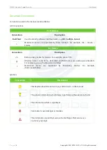
Page 5: ...tion Description Button or key names for devices For example press OK Window names menu items data table and field names are inside square brackets For example pop up the New User window Multi level menus are separated by forwarding slashes For example File Create Folder Symbols Convention Description This implies about the notice or pays attention to in the manual The general information which he...

Page 6: ...N TEST BEFORE THE INSTALLATION OF DEVICE 7 2 2 3 EQUIPMENT INSTALLATION 8 INSTALLATION CONDITIONS 8 3 1 CABLING 9 3 2 INSTALLATION 10 3 3 4 CABLE DIAGRAM 11 WIRED REMOTE CONTROL 11 4 1 WIRELESS REMOTE CONTROL 12 4 2 5 EQUIPMENT PRECAUTIONS AND MAINTENANCE 13 PRECAUTION 13 5 1 MAINTENANCE 14 5 2 6 TROUBLESHOOTING 15 ATTACHMENT 1 DEFAULT FACTORY SETTINGS 15 ATTACHMENT 2 CONNECTION DIAGRAM OF CONTROL...

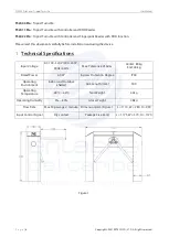
Page 7: ...y before installation and using the device 1 Technical Specifications Input Voltage AC 100 120V 200 240V 50Hz 60Hz Max Tolerance of Arms Center 80 kg End 40 kg Rated Power 60 W Ingress Protection Degree IPX4 Operating Environment Indoor and Outdoor shelter Arm Length mm 500 Operating Temperature 28ºC 60ºC Net Weight 42kg Operating Humidity 5 85 Gross Weight 48kg Flow Rate Max 30 passages minute Di...

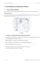
Page 8: ...anism core then tighten 3 hex screws as shown in Figure 2 1 Figure 2 1 Power on Test before the Installation of Device 2 2 1 Please make sure that the power requirements are strictly met to avoid permanent damage to the unit Input voltage AC 100 120V 200 240V Note The tripod turnstile must be connected to the ground earth 2 Power on and wait 30s for the tripod turnstile to finish the self check pr...

Page 9: ...stallation Conditions 3 1 The equipment must be installed on concrete ground ensuring that expansion bolts can be secured firmly You are suggested to install an assistant framework or fence to form a passageway as shown in Figure 3 1 Figure 3 1 Lift upwards There is a power switch in the side direction of this power supply Earth wiring terminal ...

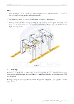
Page 10: ... line for card swiping see Figure 3 2 A warning line is suggested to prompt users to swipe cards in a distance which would greatly reduce the probability of equipment failure caused by improper operations Figure 3 2 Cabling 3 2 There are inlets in the bottom plate for cabling as shown in Figure 3 3 the unit is millimeter Power supply and communication wire should go through the inlet Cable protect...

Page 11: ...ion bolts install four expansion bolts to secure the mounting plate and use a horizontal ruler to test the levelness of the mounting plate If the mounting plate is not level adjust it by the gaskets provided Note that all the four expansion bolts must be installed properly as shown in Figure 3 4 Figure 3 4 3 Put the turnstile on the mounting plate and tighten the screws Apply screw securing glue b...

Page 12: ...trol 4 1 Dial code description The DIP switch is divided in eight dial codes from KE 1 to KE 8 Move the switch up to turn ON and down to OFF Description of function Setting Dial 0 to turn off Dial 1 to turn on Dial code function item Unmanned passage time KE 1 KE 2 KE 3 Switch Status Time Period 000 OFF OFF OFF 5S Default 001 OFF OFF ON 10s 010 OFF ON OFF 15s 011 OFF ON ON 20s 100 ON OFF OFF 30s ...

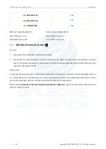
Page 13: ...he controller and a light corresponding to the button will flash slowly Then press any switch on the remote control for acquiring the information After the successful operation the light turns off Clear mode Long press the learning button on the three roller gate controller for 3 seconds The learning light stays on for a while then turns off indicating the code is cleared successfully The original...

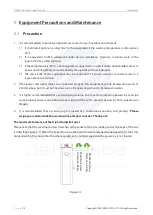
Page 14: ...power and signal cables are connected properly this equipment can be immersed in water of 250 mm deep but it must not be powered on for operating when it is immersed in water 3 It is highly recommended that a card swiping warning line to set for prompting passers by to swipe cards properly and a reasonable passage width shall be set to prevent passers by from squeezing in illegally 4 It is recomme...

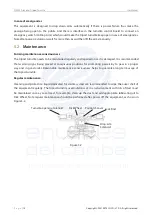
Page 15: ...egularly and repaired once it is damaged It is recommended that warning signs being placed at conspicuous positions for prompting passers by to pass in a proper way and in good order Reasonable maintenance consciousness helps to guarantee long term usage of the tripod turnstile Regular maintenance Cleaning and protection liquid dedicated for stainless steel are recommended to wipe the outer shell ...

Page 16: ...rcuit the ports K1 GND and K2 GND if the turnstile is successfully opened it would be the problem of controller In this case please refer to Attachment 2 Connection Diagram of Control Board and Access Control Panel to check the cable connection of the controller The turnstile allows people continue passing one way side during the use 1 Check the Turnstile opening Solenoid 2 Check the access contro...

Page 17: ...ZKTECO CO LTD All rights reserved Attachment 2 Connection Diagram of Control Board and Access Control Panel Warning This is a class A product In a domestic environment this product may cause radio interference in which case the user may be required to take adequate measures ...

Page 18: ...ZKTeco Industrial Park No 32 Industrial Road Tangxia Town Dongguan China Phone 86 769 82109991 Fax 86 755 89602394 www zkteco com Copyright 2021 ZKTECO CO LTD All Rights Reserved ...

Reviews:

Related manuals for TS2000 Pro Series