background image

BioSense Series Network Video Recorder                                                                                                                                                       User Manual 

P a g e

 | 76 


 Copyright©2023 ZKTECO CO., LTD. All rights reserved.


13.


User Manage 

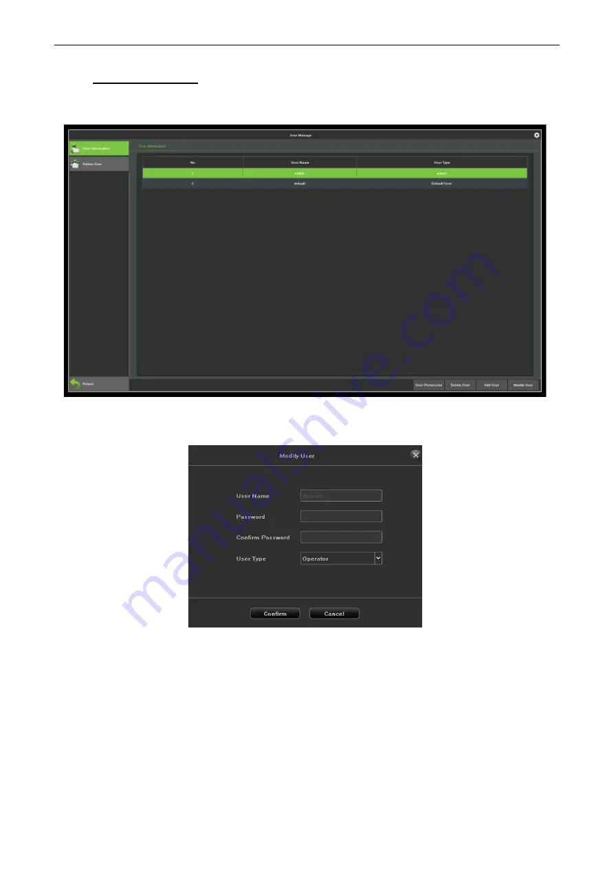
User manage interface is shown in Figure 13.1, you can modify the user information and users permission. 


Figure 13.1 User Management 


Modify Users: 

Modify the selected users information, as shown in Figure 13.2. 


Figure 13.2 Modify Users 


Add User: 

Add a new user, as shown in Figure 13.3, fill in the user name and password. 

Summary of Contents for BioSense Series

Page 1: ...uctions carefully before operation Follow these instructions to ensure that the product is functioning properly The images shown in this manual are for illustrative purposes only For further details p...

Page 2: ...e safe operation of the machine unit Device that personnel has read understood and followed the safety instructions contained in the manual In case of any conflict between terms and conditions of this...

Page 3: ...ble i in case the machine unit Device malfunctions due to any non compliance of the instructions contained in this manual ii in case of operation of the machine unit Device beyond the rate limits iii...

Page 4: ...dependent research and development of biometric verification procedures and the productization of biometric verification SDK which was initially widely applied in PC security and identity authenticati...

Page 5: ...VIEW 17 4 PLAYBACK 19 4 1 INSTANT PLAYBACK 19 4 2 PLAYBACK BY NORMAL SEARCH 20 4 2 1 RECORDING PLAYBACK 20 4 2 2 PLAYBACK BY EVENT SEARCH 22 4 2 3 PLAYBACK PICTURES 22 4 2 4 PLAYBACK EXTERNAL FILE 24...

Page 6: ...2 1 AUTOMATIC GROUPING 59 9 3 MANUAL GROUPING 59 10 SYSTEM MANAGE 60 10 1 SYSTEM INFORMATION 60 10 1 1 DEVICE INFORMATION 60 10 1 2 STREAM INFORMATION 61 10 2 CONFIGURATION MANAGEMENT 61 10 3 SYSTEM...

Page 7: ...T CONNECTION 80 14 5 3 PTZ CONNECTION 80 14 6 BASIC OPERATION GUIDE 81 14 6 1 POWER ON 81 14 6 2 POWER OFF 81 14 6 3 LOG IN 81 14 6 4 PREVIEW 82 14 7 CHANNEL MANAGEMENT 83 14 7 1 MODE SWITCH 83 14 7 2...

Page 8: ...the device Ensure environmental conditions meet factory specifications Power down the device before connecting and disconnecting accessories and peripherals 1 2 Hard Disk Installation Before you start...

Page 9: ...LTD All rights reserved 3 Connect the power data cable to the NVR and HDD 4 Close the cover and fasten it with the screws 1 2 2 NVR with 1 or 2 HDD Steps 1 Remove the cover from the NVR by unfastening...

Page 10: ...ense Series Network Video Recorder User Manual P a g e 10 Copyright 2023 ZKTECO CO LTD All rights reserved 3 Connect the power data cable to the NVR and HDD 4 Close the cover and fasten it with the sc...

Page 11: ...p the video output defaults to multiple screen output mode 2 1 2 Shut down Option 1 Press the power key on front panel to shutdown the device should be supported by the device Option 2 Click Start Shu...

Page 12: ...n to log in 2 3 Using Guide The Guide starts once login as shown in Figure 2 3 Figure 2 3 Language Setting Operating the Guide 1 The Guide can walk you through some basic settings of the NVR If you do...

Page 13: ...reserved 3 After the display setting click Next button to enter the Network Setting window as shown in Figure 2 5 Figure 2 5 Network Setting 4 After the network setting click Next button to enter the...

Page 14: ...o perform associated settings as shown in Figure 2 7 Figure 2 7 Menu Operation 2 4 1 Begin setup Click the icon it will pop up the interface as show in Figure 2 8 Figure 2 8 Begin Setup 1 Logout Click...

Page 15: ...w mode there are hide icons on the screen of each channel which shows when you move the mouse to the bottom of channel Icons Description Icons Description Open Close PTZ Show Hide Smart detection Snap...

Page 16: ...al length focus aperture amplification and narrow in PTZ operation interface and adjust the speed of PTZ as shown in Figure 3 3 See below the detailed operation of PTZ control part Figure 3 3 PTZ Cont...

Page 17: ...64 Split Screen Sound Adjust Cruise on Setting Linkage Preview Page Up Page Down Table 3 2 Other Function Description 3 3 Using the Mouse in Preview Figure 3 6 Preview Name Description PTZ Control Op...

Page 18: ...Screen Select and enter 25 Split Screen mode 36 Split Screen Select and enter 36 Split Screen mode 64 Split Screen Select and enter 64 Split Screen mode Previous Screen Switch to the previous screen N...

Page 19: ...O LTD All rights reserved 4 Playback 4 1 Instant Playback Purpose Playback the recorded video files of a specific channel in the live view mode Steps Choose a channel in live view mode and click the b...

Page 20: ...terface as shown in Figure4 2 Figure 4 2 Normal Playback Interface Playback by Time Purpose Playback video files recorded in specified time duration Multi channel simultaneous playback is supported St...

Page 21: ...it is displayedas Playback Interface You can use the toolbar in the bottom part of Playback interface to control playing progress as shown in Figure 4 4 Figure 4 4 Playback Toolbar Button Operation Bu...

Page 22: ...ct the Retrieving type There are many types you can select such as Count Alarm Motion Across the line Regional Alarm detection and object left Loss etc 3 Select the human and Vehicle 4 Click the Searc...

Page 23: ...utton to search for the capture picture 9 Check the check box after the picture listed then click to view the picture 10 The toolbar in the bottom of playback interface can be used to control playing...

Page 24: ...rnal File Purpose Perform the following steps to look up and playback files in the external devices as shown in Figure 4 7 Figure 4 7 USB Playback Interface Steps 1 Enter the playback interface 2 Sele...

Page 25: ...Setting interface as shown in Figure 5 1 click Channel Manage Regular config PTZ Setting Figure 5 1 PTZ General Setting Interface 2 Set the parameter of PTZ Channel Choose the channel Protocol Choose...

Page 26: ...e directional button to wheel the camera to the location where you want to set preset and the zoom and focus operations can be recorded in the preset as well 2 Setting the name of preset click button...

Page 27: ...he next key point to the patrol 5 After finish setting click Exit button 5 2 3 Pattern Setting Purpose Patterns can be set by recording the movement of the PTZ You can call the pattern to make the PTZ...

Page 28: ...TD All rights reserved 6 Search Purpose The record files can be backup to various devices such as USB devices USB flash drives USB HDDs Click icon to enter the local backup interface as shown in Figur...

Page 29: ...up 5 Click Search button to view the file size 6 Click Start Backup button to start the backup show as Figure 6 2 6 2 Video Retrieval Figure 6 3 Video Backup Interface Steps 1 Select the Channel to ba...

Page 30: ...add has already been activated Steps 1 Click icon enter into the Channel Connecting interface as shown in Figure 7 1 Figure 7 1 Quick Adding IP Camera Interface 2 Click Add Channel button it will auto...

Page 31: ...configure OSD settings 3 Local Channel Name setting 1 Check the check box before Show Local Channel Name then enter the Local Channel Name in the text field 2 Click Save button the name that enter wi...

Page 32: ...served Figure 7 3 OSD Configuration Interface 5 Select the Date Time Format should be supported by the camera 6 Image Parameters Adjust the Brightness Contrast Saturation and Hue of the channel as sho...

Page 33: ...1 Enter the media parameters interface as shown in Figure 7 6 Figure 7 6 Recording Parameter 2 Set the video parameter Channel Select Select the channel of camera to configure the encoding type Stream...

Page 34: ...r PTZ The configuring of the PTZ parameters should be done before you control the PTZ camera Steps 1 Enter the PTZ Setting interface as shown in Figure 7 8 2 Set the parameter of PTZ Channel Choose th...

Page 35: ...8 PTZ General Setting Interface 7 2 5 Tour Grouping The role of setting tour Grouping is to group the channel and preview can group according to a standard as shown in Figure 7 9 that is group accord...

Page 36: ...meters of motion detection Figure 7 10 Motion Detect Mode The default is Camera when NVR support smart smart detection can switch mode to NVR Sensitivity Can increase the accuracy of the motion detect...

Page 37: ...P a g e 37 Copyright 2023 ZKTECO CO LTD All rights reserved Figure 7 11 Zone Setting Arming Plan Set the schedule that needs arming as shown in Figure 7 12 Figure 7 12 Planning Linkage Setting Choose...

Page 38: ...g e 38 Copyright 2023 ZKTECO CO LTD All rights reserved Figure 7 13 Linkage Clear all One click to clear the motion detection area on the screen setbefore 7 3 2 Video Lost Video lost configuration in...

Page 39: ...g e 39 Copyright 2023 ZKTECO CO LTD All rights reserved Channel Choose the channel number Planning Set the arming schedule of video loss as shown in Figure 7 15 Figure7 15 Planning Linkage Set the li...

Page 40: ...ps 1 Enter Video Mask Alarm interface of channel parameter and choose a channel you want to setup Video Mask Alarm as shown in Figure 7 17 Figure7 17 Video Shelter 2 Set the video mask alarm handling...

Page 41: ...g e 41 Copyright 2023 ZKTECO CO LTD All rights reserved Figure 7 18 Planning 4 Setup the linkage operation of the channel as shown in Figure 7 19 Figure 7 19 Linkage 5 Click Save button to save the se...

Page 42: ...d Steps 1 Enter the Privacy Mask Settings interface as shown in Figure 7 20 Figure 7 20 Video Mask 2 Select the camera to set privacy mask 3 Click the check box of Enable Privacy Mask to enable this f...

Page 43: ...d local detection modes based on the actual capacity of the product scene changes only support the local detection mode 7 4 2 Enable Smart Analysis Some NVR models disable local smart by default To en...

Page 44: ...cene selection 3 Alert area requirements the warning area used for intelligent analysis is required to exceed more than 1 8 of the video screen area if it is cordon the distance between the sides of t...

Page 45: ...anually draw two lines Detect Type Set the detection object to be human or vehicle and an alarm will be triggered when the object detected in the area is the set value Arming That is set the deploymen...

Page 46: ...e Advanced Setting A B Acquiesce is A area to B area to increase counting A B area location on both sides of detection line can be exchanged B A Increment Count or Flow Count Result A Count of B B Cou...

Page 47: ...Figure 7 26 Alarming 7 4 3 5 Counter Statistics The purpose of this page is to calculate the number of people vehicles counted during the activation of the target counting function by time period whi...

Page 48: ...ct Left Lost The purpose of this page is to configure the relevant parameters so that more than the proportion of objects in the set detection area lost left over time detection time that goods detect...

Page 49: ...nes Detection Type objects loss objects left objects loss or left three types Ratio Moving objects in the screen than the size of the set when the size can be used as items Detect Time detected items...

Page 50: ...in the set detection area over time detection zone detection alarm occurs Interface shown in Figure 7 31 the following page describes the main parameters of the setting method Figure 7 31 Area Detecti...

Page 51: ...once it detects that a target enters the monitored zone Target leave represents that the camera will trigger the alarm once it detects that a target leave the zone Target enter or leave represents th...

Page 52: ...display the set rules and test results in the preview interface Arming That is set the deployment time the default is all daydeployment Linkage You can enter the linkage configuration page when the a...

Page 53: ...ngle moves with the target crossing the cordon Figure 7 34 Line Crossing 7 5 Channel Zero Setting 7 5 1 Parameter config Parameter config interface is shown in Figure 7 35 then set the related channel...

Page 54: ...Series Network Video Recorder User Manual P a g e 54 Copyright 2023 ZKTECO CO LTD All rights reserved 7 5 2 Channel Config The Channel config Interface is shown in Figure 7 36 Figure 7 36 Channel Conf...

Page 55: ...iguration interface to configure the recording parameters as shown in Figure 8 1 Figure 8 1 Record Setting Interface 2 Select the Channel you want to configure 3 Select the Record Mode 4 Click Setting...

Page 56: ...BioSense Series Network Video Recorder User Manual P a g e 56 Copyright 2023 ZKTECO CO LTD All rights reserved Figure 8 2 Arming Schedule 8 2 Manual Operation Figure 8 3 Manual Operation...

Page 57: ...BioSense Series Network Video Recorder User Manual P a g e 57 Copyright 2023 ZKTECO CO LTD All rights reserved 8 2 1 Snapshot The snapshot interface as shown in Figure 8 3 Figure 8 4 Snapshot...

Page 58: ...ment Process after HDD Full There are Auto Overwrite and Stop Recording two ways the default is Auto overwrite SMART Processing There are Ignore error continue recording and Error happen stop recordin...

Page 59: ...nce of hard disk default to video in 2 hard disk video in one hard disk first 32CH of the video channel the remaining channel video in another hard disk video 9 3 Manual Grouping Manual grouping funct...

Page 60: ...ter the system manage interface this part includes six parts altogether note the following instructions 10 1 System Information Can view the device information stream info and online users 10 1 1 Devi...

Page 61: ...rved 10 1 2 Stream Information View the stream status of the current device as shown in Figure 10 2 Figure 10 2 Stream Information 10 2 Configuration Management As shown in Figure 10 3 can export the...

Page 62: ...in Figure 10 4 Figure 10 4 System Upgrade NVR Upgrade Click Browse select to upgrade the file and then the system will automatically restart after upgrading 10 4 Auto Maintenance Can set the maintenan...

Page 63: ...e Setting Device time Can manually modify the device time set the time clickModify then save time Data Format Set the data format Time Zone Switch time zones the page will pop up a new date and time t...

Page 64: ...me Manual Timing Click Manual Timing button adjust the IPC time as same as device time Auto Timing Enable the auto timing the IPC will be timing when it is different tothe device time Reconnect Timing...

Page 65: ...tchannels Language Select Can modify the system language of NVR need to restart to take effect Resolution Can modify the local monitor resolution of NVR need monitor support it come into effect immedi...

Page 66: ...ual P a g e 66 Copyright 2023 ZKTECO CO LTD All rights reserved Figure10 9 IPC protocol Management Auxiliary User Open close function default to close restart device to open Mouse Speed Adjust the spe...

Page 67: ...C Address Show the physical address of the the current network interface unchangeable DHCP When open it IP mask the gateway can not be set if the current DHCP is effective then it will obtain new IP m...

Page 68: ...o take effect UPnP status is defaulted to ineffective state it will obtain the external IP address after take effect 11 2 3 DDNS Setting The default is disable DNS status each set column can not be se...

Page 69: ...mail Setting The settings in this page is used with Email Linkage in the Linkage Setting the sender email address and password the recipient email address SMTP server address and port information need...

Page 70: ...ng field icon Let the sender mailbox to send mail to the recipient s mailbox the success or failure will pop up tips Note use Email linkage function need to ensure a good network environment then the...

Page 71: ...As shown in Figure 11 7 can monitor the network traffic of the current device Figure 11 7 Network Flow 11 5 Network Test The network test interface as shown in Figure 11 8 Figure 11 8 Network Test NI...

Page 72: ...nse Series Network Video Recorder User Manual P a g e 72 Copyright 2023 ZKTECO CO LTD All rights reserved Network Wireshark Click browse set up storage paths clickWireshark backup then complete the ba...

Page 73: ...pages of this module the following instructions respectively 12 1 Alarm Input The Alarm input interface as shown in Figure 12 1 Figure 12 1 Alarm Input Alarm Input Select channel Alarm Input Name Edi...

Page 74: ...Network Video Recorder User Manual P a g e 74 Copyright 2023 ZKTECO CO LTD All rights reserved Figure12 2 Arming Schedule Linkage Way Choose the type of alarm linkage as shown in Figure12 3 Figure 12...

Page 75: ...ense Series Network Video Recorder User Manual P a g e 75 Copyright 2023 ZKTECO CO LTD All rights reserved 12 2 Exception The Abnormal Setting interface as shown in Figure 12 4 Figure12 4 AbnormalSett...

Page 76: ...anage User manage interface is shown in Figure 13 1 you can modify the user information and users permission Figure 13 1 User Management Modify Users Modify the selected users information as shown in...

Page 77: ...eo Recorder User Manual P a g e 77 Copyright 2023 ZKTECO CO LTD All rights reserved Figure 13 3 Add User Delete Users Can delete the selected users except admin and default users User Authority Set th...

Page 78: ...tial installation please check whether HDD has been installed The number of HDD you can install depends on the number of the SATA interface Note 1 Our device will format the HDD once it boot up please...

Page 79: ...4 In pause mode click this button to resume the play Fast Backward Playback Multiple play speed or backward play Previous Next Record Play the next or previous recorded video Power Light Power Red lig...

Page 80: ...both open type and close type 2 Alarm detector s Ground terminal and DVR s Ground terminal are different 3 Alarm detector s ON terminal should be connected to the DVR s alarm input interface 4 Alarm d...

Page 81: ...hardware automatically cameras monitors etc it could last for about 20 Seconds You will hear beep sound if the whole process is completed DVR will set itself to multi screen real time surveillance mo...

Page 82: ...time you log into the system successfully 14 6 4 Preview After you log into the system it is in live mode You can find system date time channel s name etc The Preview GUI There is a Start button on t...

Page 83: ...nel button and click Refresh button to search out the IPCs in the LAN and tick the checkbox to select the IPCs then click Add button to add them to the video recorder Click Add Channel button and sele...

Page 84: ...ow to control PTZ 1 Go to the preview interface left click the mouse on PTZ channel the menu will popup click the PTZ icon the PTZ control interface will display 2 Configure the parameters Speed The r...

Page 85: ...Search Mode Any Conditions in 5 all conditions in 5 5 Search Filter Normal Motion Detection Alarm Detection Offline Detection 6 Play Window The playback video display here sorted by channels 7 Playbac...

Page 86: ...cess Check whether the DVR NVR is on the network by checking network LED on front panel Light on indicates connected otherwise lose connection Open one browser and type the NVR DVR IP and HTTP port in...

Page 87: ...Manual P a g e 87 Copyright 2023 ZKTECO CO LTD All rights reserved You can switch between different channels for preview control PTZ and modify camera parameters You can switch between different chann...

Page 88: ...BioSense Series Network Video Recorder User Manual P a g e 88 Copyright 2023 ZKTECO CO LTD All rights reserved You can view and modify NVR DVR configuration System Settings Device Parameters...

Page 89: ...BioSense Series Network Video Recorder User Manual P a g e 89 Copyright 2023 ZKTECO CO LTD All rights reserved Channel Management Network...

Page 90: ...BioSense Series Network Video Recorder User Manual P a g e 90 Copyright 2023 ZKTECO CO LTD All rights reserved Alarm Hard Disk Management...

Page 91: ...BioSense Series Network Video Recorder User Manual P a g e 91 Copyright 2023 ZKTECO CO LTD All rights reserved Intelligence...

Page 92: ...ss 14 10 3 1 Mobile Phone Application Access 1 Click Start Menu Network Manage Basic Setting Platform Setting AntarView Pro and enable this function 2 Scan APP QR code to download and install applicat...

Page 93: ...2023 ZKTECO CO LTD All rights reserved 14 10 3 2 PC Application Access 1 Install VMS on your computer 2 Enter Resource Management Device Manage to search add delete modify network devices Type in devi...

Page 94: ...BioSense Series Network Video Recorder User Manual P a g e 94 Copyright 2023 ZKTECO CO LTD All rights reserved...

Page 95: ...h this product description This Quick Setup Guide is for quick reference to certain DVR NVR models the specific operations of each product are not listed Please contact us if you have any operational...

Page 96: ...t 2023 ZKTECO CO LTD All rights reserved ZKTeco Industrial Park No 32 Industrial Road Tangxia Town Dongguan China Phone 86 769 82109991 Fax 86 755 89602394 www zkteco com Copyright 2023 ZKTECO CO LTD...

Reviews: