background image

Installation and Network Configuration 

2 Installation and Network Configuration 

2.1 Hardware Installation 


Installation Notices: 

(1)


Read through the guide for installation prior to installation. 

(2)


Check whether any component is missing against the packing list, if yes, 

please contact your supplier. 

(3)


Wire during power off. If the camera does not function normally during 

operation, please cut off the power before check. 

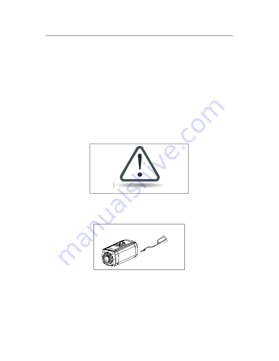
Do not connect cables when power is on!


Notice

: The wiring during power on may seriously damage the camera, 

which will be disqualified from the guarantee. 

DC12V/1A


(4)


Use the power supply of DC12V and no lower than 1A for the camera or PoE 

power supply (optional). Too high or low voltage, or AC power supply may 

cause the abnormal operation of the camera. 

Summary of Contents for ZKIP3 Series

Page 1: ...Manual for ZKIP3 Series Standard Box IP Camera Document Version 1 7 Date 2012 12 Introduction This document mainly introduces the functional features installation process and access methods of ZKIP3 series IPC ...

Page 2: ...depend on the actual product Since the product is subject to updating our company is not responsible for any difference from this guide and not liable for any dispute over different technical parameters from this guide The project is subject to any change without notice To learn more please visit our company s website www zkivision com or local office ...

Page 3: ...ers 2 1 4 Product Appearance 4 1 5 Connecting Terminals 5 1 6 Basic Procedure 8 2 Installation and Network Configuration 9 2 1 Hardware Installation 9 2 2 Network Connection 12 3 Accessing device 14 3 1 Using WEB Browser 14 3 2 Using RTSP Media Player 15 3 3 Using Mobile Devices 17 3 4 Using Video Surveillance Software 19 ...

Page 4: ......
Page 5: ...to different environment the series products can be configured with protective covers in various specifications easily installed and operated and are applicable to a variety of occasions for video surveillance systems as well as to all weather and all environment use 1 2 Product Features Hi3512 high performance multimedia processor supporting H 264 Main Profile video coding Dual code stream suitab...

Page 6: ...amic domain name system DDNS Network time synchronization NTP HD cam to support the browsing by 14 users simultaneously 4 in primary code stream and 10 in secondary code stream SD cam to support the browsing by 20 users simultaneously 10 in primary code stream and 10 in secondary code stream 1 3 Technical Parameters Product Name Standard box IP camera Product Model ZKIP370 ZKIP350 Cam Properties I...

Page 7: ... Dynamic Mode adjustable HD Brightness Saturation Contrast Image Up Down Image Left Right adjustable Terminal funcional Audio Interface 1 Mic input and 1 linear output optional Alarm Input 1 alarm input normally opened or normally closed optional Alarm Output 1 switch output maximum working voltage AC 120V 1A DC 24V 1A Motion Detection Allow 4 independent detection areas Control Interface 1 RS485 ...

Page 8: ... Power DC 12V 1A POE Ethernet power supply comply with 802 3af regulation optional Maximum Power Consumption 8W Working Temperature 20 55 C Working Humidity 10 80 RH 1 4 Product Appearance Diagram installation seat of lens base microphone hole camera Dimensional drawing in mm Right View ...

Page 9: ...wer supply of DC 12V and no lower than 1A Do not use any different power supply as it may damage the camera 2 Network Interface LAN 10 100M self adapting Ethernet interface is used to connect the camera with various network equipments such as switch router and hub When it is connected to 10M network the orange lamp is on When it is connected to 100M network the green lamp is always on ...

Page 10: ...its factory default The default user s name is admin the default password is admin and the default IP address is 192 168 1 88 4 Alarm Interface COM NO IN GND Connect to alarm input and alarm output When the camera receives an alarm from alarm output or Web motion detection this interface can send a signal to alarm output to realize real time monitoring and overall protection while triggering a rem...

Page 11: ... default connection is as follows switch COM NO alarm output terminals alarm output device power supply of alarm output device Schematic Diagram of Alarm Output Normally Opened Connection 5 RS485 Interface 485 485 Supports standard 485 PTZ protocols for remote device control The camera can be turned remotely and monitored in all directions The relevant parameters are set as detailed in WEB Server ...

Page 12: ...r computer IP is in a network section different from camera IP please set it to the same network section as camera IP such as 192 168 1 87 4 Log in the camera through client software or browser to check whether the video functions normally 5 Adjust the code stream and other video parameters 6 Modify the network parameters of camera and reboot the device 7 Repeat Step 3 8 Revisit the camera through...

Page 13: ... your supplier 3 Wire during power off If the camera does not function normally during operation please cut off the power before check Do not connect cables when power is on Notice The wiring during power on may seriously damage the camera which will be disqualified from the guarantee DC12V 1A 4 Use the power supply of DC12V and no lower than 1A for the camera or PoE power supply optional Too high...

Page 14: ...revent any accidental contact from damaging the camera Uncovered cable should be less than 5mm 8 Mount the relay equipment in the middle to avoid signal attenuation when the straight communication distance from the camera to the incoming equipment exceeds 80m Please use repeater when exceeding 80m 9 When RS485 is employed if the communication distance exceeds 100m the final equipment on the 485 bu...

Page 15: ...tion 11 11 Use the camera in the working conditions Ambient temperature 20 55 ambient relative humidity 10 80 RH 12 Please keep the lens and transparent cover clean If the transparent cover is dirty please wipe it with clean soft cloth ...

Page 16: ... network in two ways The first way is to connect to the network by means of Ethernet cable and the second way is to connect to wireless network optional Connect by Ethernet Cable 1 Use Ethernet cables to connect the device to network or directly to computer 2 Connect the power supply of the device 3 During normal connection if it is a 10M network the orange lamp is always on if it is a 100M networ...

Page 17: ...ser Manual 2 If the device is in a network section different from computer refer to How to Visit IPC on Internet in WEB Server User Manual for the connection during different network sections Connect to Wireless Network Before starting the wireless network connect the IPC to network by Ethernet cable visit the device through IE browser enter Network Setting interface and set the wireless network c...

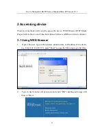
Page 18: ...RTSP Media Player Mobile Device and Video Surveillance Software ZKiVision client software 3 1 Using WEB Browser 1 Open a browser type in the dynamic domain name or IP address of the device e g http 192 168 80 123 press Enter to open the following login interface 2 Type in user s name and password and click OK and the guide page will show as below ...

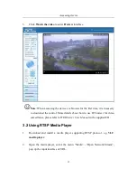
Page 19: ...download the control More details about how to use IE browser for video surveillance please refer to WEB Server User Manual in the supplied CD 3 2 Using RTSP Media Player 1 Download and install a media player supporting RTSP protocol e g VLC media player 2 Open the media player select the menu Media Open Network Stream pop up the input interface of URL ...

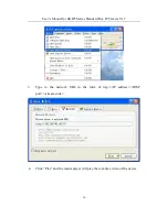
Page 20: ...anual for ZKIP3 Series Standard Box IP Camera V1 7 16 3 Type in the network URL in the form of rtsp IP address RTSP port stream code 4 Click Play and the media player will play the real time video of the device ...

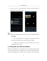
Page 21: ...edia player for video surveillance please refer to WEB Server User Manual in the supplied CD 3 3 Using Mobile Devices If it is necessary to use mobile phone for video surveillance please firstly ensure the device can be accessed on Internet Please refer to ZKiVision User Manual Mobile Version 1 Install the surveillance software into your mobile phone 2 Click the icon ZKiVision to enter the softwar...

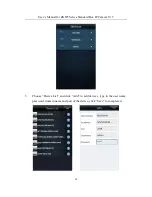
Page 22: ...ser s Manual for ZKIP3 Series Standard Box IP Camera V1 7 18 3 Choose Device List and click Add to add devices type in the user name password domain name and port of the device click Save to complete it ...

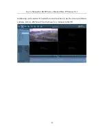
Page 23: ... for watching video please consult with your internet service provider for specific charges 3 Please refer to ZKiVision User Manual Mobile Version in the supplied CD for more details 3 4 Using Video Surveillance Software ZKiVision Client Software is our company s free video surveillance software which can help manage and monitor multiple devices in a real time manner Install the software in the su...

Page 24: ...s Manual for ZKIP3 Series Standard Box IP Camera V1 7 20 monitoring can be started If needed to learn about how to use the video surveillance software refer to ZKiVision Client Software User Manual in the CD ...

Reviews: