


24
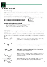
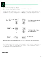
-The display requested rotation of the rim tire. Mark
with chalk a reference sign on the adapter and rimorder
that the rim
can be remounted in the same position on the machine
(Use index on the spindle)
-With the aid of tire remover, turn the tire on the rim
by 180
0
-Refit the rim on the flange in the previous position.
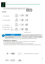
Right display: value % of possible reduction of the
unbalance referred to the current wheel situation.
Left display: current static unbalance value in grams. It
is the value which can be reduced by a wheel-rim rota-
tion.
Turn the wheel until the out LED’s light up:
Mark the tire at top point (12 O’clock)
Likewise mark the rim in correspondence to the position
Indicated by the inner LED’s
In the example given, an 80% reduction of the static
unbalance of 45grams is obtained with a residue of about 9grams
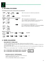
VISUAL WHEEL EXAMINATION
In certain cases it is advisable to rotate the wheel with guard open in order to inspect the condition of the
tread.
Press “F” while with the other hand press “START”
A complete measuring spin is performed. At the end of the cycle, the function is automatically
disabled.
7
SELF CALIBRATION
Summary of Contents for ZI-RWM99
Page 3: ...3 Abb 1 Abb 2 Abb 3 1 3 2 4 9 11 8 6 7 13 12 15 14 10 5...
Page 5: ...5 Abb 6...
Page 28: ...28 10 EXPLOSION DRAWINGS CIRCUIT DIAGRAM...
Page 29: ...29...
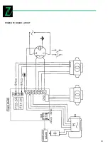
Page 30: ...30 POWER PC BOARD LAYOUT...
Page 31: ...31 REPLACE THE POWER PC BOARD...