Zipper Mowers ZI-RWM99 Operation Manual Download Page 20


20 


Before connecting the balancer to the power supply, check the voltage that showing on the nameplate 
at the back of machine.  

The machine mains supply cable should be fitted with a plug conforming to current regulations. 

It is advisable to provide the machine with its own electrical connection through a suitable circuit 
breaker. 

When connection is made directly to the mains control panel, without using any plug, it is advisable to 
padlock the main switch of the balancing machine so that its use is limited only to authorized person-
nel. 


WHEEL MOUNTING 

The machine is supplied as standard with a universal cone adapter. The adapter body build-in spring 
cannot be disassembled from the spindle. The threaded end is removable in order to allow mounting 
alternative adapters. 


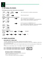
PRESETTING OF DIMENSIONS 


Press distance “a” on the inside of the wheel from the machine measuring with the 
special gauge. Increment pitch 0.5 cm Full scale 25cm.                                              


Preset the nominal width which is generally given on the rim, or else measuring width 
”b” with the caliper gauge. 


Increment pitches: 

-unit of measurement mm: 5mm 

-unit of measurement inch: 0.25’’ 

the following is displayed:   .2 for 1/4’’ 

.5 for 1/2’’ 

.7 for 3/4’’ 


Preset the nominal diameter “d” stamped on the type: 

Increment pitches: 

-unit of measurement mm: 12/13mm 

-unit of measurement inch: 0.5’’  


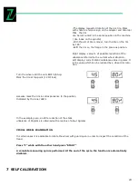
MANUAL PRESETTING WITH GAUGE EXTENSION 


The extension increases the range of measurements of the gauge by 6cm (Abb. 4B) and allows distance meas-
urement also when the rim is of special shape (Abb. 4A). 

Proceed as follows: 

-Fit the extension on the distance gauge 

-Proceed to the distance measurement in the modes described earlier on. 

-After reading value ”a” on the index, reset the gauge to “0” and manually preset value ”a+6”.  

-Press the diameter and width manually as described in Abb. 2 


Abb. 2 

Abb. 3 

Abb. 4 

Summary of Contents for ZI-RWM99

Page 1: ...ne EN Operation Manual Wheel balancer ZI RWM99 EAN 9120039239118 DE Bedienungsanleitung und Sicher heitshinweise vor Erstinbetrieb nahme lesen und beachten EN Read the operation manual carefully befor...

Page 2: ...tungsanleitung Ihrer Maschine aufmerksam durch und machen Sie sich mit den Bedienele menten der Maschine gut vertraut um die Maschine ordnungsgem zu be dienen und so Sch den an Mensch und Maschine vor...

Page 3: ...3 Abb 1 Abb 2 Abb 3 1 3 2 4 9 11 8 6 7 13 12 15 14 10 5...

Page 4: ...4 Abb 4 POSITIOINIERUNG UND KORREKTUR DER AUSSENSEITE POSITIONING AND CORRECTION ON THE OUTSIDE POSITIOINIERUNG UND KORREKTUR DER INNENSEITE POSITIONING AND CORRECTION ON THE INNSIDE Abb 5 Abb 6 A B...

Page 5: ...5 Abb 6...

Page 6: ...r Produkte k nnen Abbildungen und Inhalte geringf gig ab weichen Sollten Sie jedoch Fehler feststellen informieren Sie uns bitte Achtung Technische nderungen vorbehalten Urheberrecht 2011 Diese Dokume...

Page 7: ...den Lichtverh ltnissen nach Ein bruch der D mmerung sollten Sie nicht mehr arbeiten Bei M digkeit Unkonzentriertheit bzw unter Einfluss von Medikamenten Al kohol oder Drogen ist das Arbeiten mit der M...

Page 8: ...twortlich diese unbrauch bar machen indem Sie die Stromanschl sse trennen TRANSPORTATION Die Wuchtmaschine muss in der Originalverpackung transportiert werden und sich in Position wie in der Verpackun...

Page 9: ...ecker nach aktuell g ltigen Verordnungen eingebaut werden Es ist ratsam die Maschine mit eigenen elektrischen Anschluss durch einen geeignete Schutzschalter zu Unterst tzen Reifenwuchten Die Maschine...

Page 10: ...e das Messger t auf 0 und den manuell einge stellten Wert a 6 Dr cken Sie die Durchmesser und Breite manuell 5 OPTIONALE FUNKTIONEN Voreinstellung gespeichert auch wenn die Maschine ausgeschaltet ist...

Page 11: ...ichte angebracht werden m ssen die ver f gbaren Funktionen Platz zeigen wo die Korrektur Gewichte in Einzeltitel abweichend von den nor malen Platz Dr cken Sie ALU und F um die gew nschten Funktionen...

Page 12: ...sein Zur Verschiebung der Unwucht mit voreingestellten Abmessungen dr cken Sie die Taste C zugeordnet Wenn ein Spin ist bereits gemacht das System berechnet automatisch die Unwucht sonst dr cken Sie d...

Page 13: ...Gram Dies ist der Wert der durch eine Rad Felgen Rotation reduziert werden kann Drehen Sie das Rad bis das u ere LED aufleuchtet Markieren Sie den Reifen auf dem oberen Ende 12 Uhr Markieren Sie die...

Page 14: ...f st ndig leuchtend bergeht Addieren Sie ein Gewicht von 100 Gramm auf der Au enseite in irgendei ner kantigen Position Es ist wichtig dass am Rad w h rend des Drehens nicht geklopft wird Maschine kal...

Page 15: ...Garantie gem folgenden Bedingungen Die Garantie umfasst die unentgeltliche Beseitigung aller M ngel an der Maschine nach Ma gabe der nachfolgenden Regelungen welche die ordnungsgem e Funktion der Mas...

Page 16: ...atzteile die ideal aufeinander abgestimmt sind Die opti male Passgenauigkeit der Teile verk rzen die Einbauzeiten und erhalten die Lebensdauer Bestelladresse sehen Sie unter Kundendienstadressen im Vo...

Page 17: ...DETAILS Motor power 185 W Power supply voltage 230V Weight 90 kg Rim Width 1 5 20 Rim diameter 10 24 Wheel weight max 70 kg Measurement accuracy 1g Measuring time 60 sek Noise Level 70 dB Packaging 57...

Page 18: ...k laces etc when operating the machine They might be catched by rotating parts and cause serious injuries Wear long close fitting trousers and sturdy non slip footwear Use proper safety clothing and d...

Page 19: ...ackage itself The packed machine should be moved by means of a forklift truck of suitable capacity Insert the forks at the points shown in Abb 2 CONTROL PANEL 1 Digital display of inside unbalancing v...

Page 20: ...S Press distance a on the inside of the wheel from the machine measuring with the special gauge Increment pitch 0 5 cm Full scale 25cm Preset the nominal width which is generally given on the rim or e...

Page 21: ...L BALANCING MEASUREMENT OF UNBALANCE To make a measuring spin close the guard alternatively press START if selected In a few seconds the wheel is brought up to speed and a new braking the amounts of u...

Page 22: ...ones Press ALU and F to select the required functions SEE OPTIONAL FEATURES The amounts of unbalance are displayed correct on the basis of the selected correction position NORMAL Balancing of steel o...

Page 23: ...h preset dimensions press key C If a spin has already been made the system automatically recalculates the unbalance otherwise press the START for a new spin OPTIMIZATION OF UNBALANCE The functions ser...

Page 24: ...in grams It is the value which can be reduced by a wheel rim rota tion Turn the wheel until the out LED s light up Mark the tire at top point 12 O clock Likewise mark the rim in correspondence to the...

Page 25: ...to being steady Add a weight of 100 grams on the outside in any angular position It is important not to knock the wheel during this spin Machine calibrated Remove the master weight from the wheel and...

Page 26: ...el is not balanced This does not depend on incorrect indication of the machine but only on a faulty mounting of the wheel on the adapter i e in the two mountings the wheel has assumed a different posi...

Page 27: ...ft the motor until the belt is correctly tensioned 3 Carefully retighten the 4 motor mounting screws Check then when the belt is running there is no side deviation Place the accessory shelf back in po...

Page 28: ...28 10 EXPLOSION DRAWINGS CIRCUIT DIAGRAM...

Page 29: ...29...

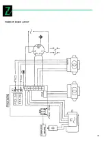
Page 30: ...30 POWER PC BOARD LAYOUT...

Page 31: ...31 REPLACE THE POWER PC BOARD...

Page 32: ...00277 Ausstellungsdatum issuing date 08 06 2010 Ausstellende Beh rden Issuing authorities authorities AVTECH House Arkle Avenue Stanley Green Trading Estate Handforth Cheshire SK9 3RW Hiermit erkl ren...

Reviews: