


19
The machine must be operated by trained staff and can only be used for purpose described in this
manual.
Do not wear unfit clothes such as large clothes with flounces, tires, etc; which could get caught by
moving parts of the machine.
f.
After use:
Do not modify the machine without manufacturer’s advice.
Do not use strong jet of compressed air for cleaning.
Use Alcohol to clean plastic panels, but avoid contaminating important board inside.
If the machine is not to be used any more, owners are suggested to make it unusable by removing
the power supply connections, emptying the oil tank and disposing the liquids in accordance with the
national laws in force.
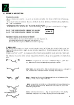
TRANSPORTATION
The wheel balancer must be transported in its original packing and kept in the position shown on the
package itself.
The packed machine should be moved by means of a forklift truck of suitable capacity. Insert the
forks at the points shown in Abb. 2
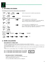
CONTROL PANEL
1
Digital display of inside unbalancing value
2
Digital display of out unbalancing value
3
Indicator, inside unbalancing position
4
Indicator, outside unbalancing position
5
Indicator, correction mode selected
6
Push button for unbalancing value <5g / 0.035
7
Push button, correction mode selection
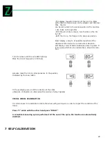
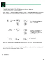
8
Push button, recalibration/ self-calibration
9
Push button, manual input of DISTANCE
10
Push button, manual input of WIDTH
11
Push button, manual input of DIAMETER
12
Push button, optimization of unbalance
13
Push button, Shift between DYNAMIC/STATIC
14
Push button, Start
15
Push button, Emergency stop
4
INSTALLATION
The machine must be installed on level ground and there is no need to anchor the machine to the
floor for correct operation
ELECTRICAL CONNECTION:
Electrical connection must be done by specialized people
Abb. 1
Summary of Contents for ZI-RWM99
Page 3: ...3 Abb 1 Abb 2 Abb 3 1 3 2 4 9 11 8 6 7 13 12 15 14 10 5...
Page 5: ...5 Abb 6...
Page 28: ...28 10 EXPLOSION DRAWINGS CIRCUIT DIAGRAM...
Page 29: ...29...
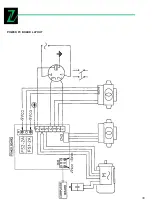
Page 30: ...30 POWER PC BOARD LAYOUT...
Page 31: ...31 REPLACE THE POWER PC BOARD...