background image

HydroTap Installation and Operating Instructions  

                              Page 5 of 20

In addition to normal tools, the following will be required:

•  50mm diameter sheet metal hole punch for sink tops. (not supplied)

•  50mm diameter hole saw for timber bench tops. (not supplied)

•  Nut runner tube spanner (supplied) for fixing tap assembly.

 Special tools required

Step A - Installing the (Boiling / Chilled) HydroTap outlet


(see 

P10-13)

1.   Make sure that the tap location will allow the nozzle outlet, as well as the 

vent outlet, to drain into the sink. (see outlet details P10)

2.   Cut a 50mm hole in the bench / sink top.

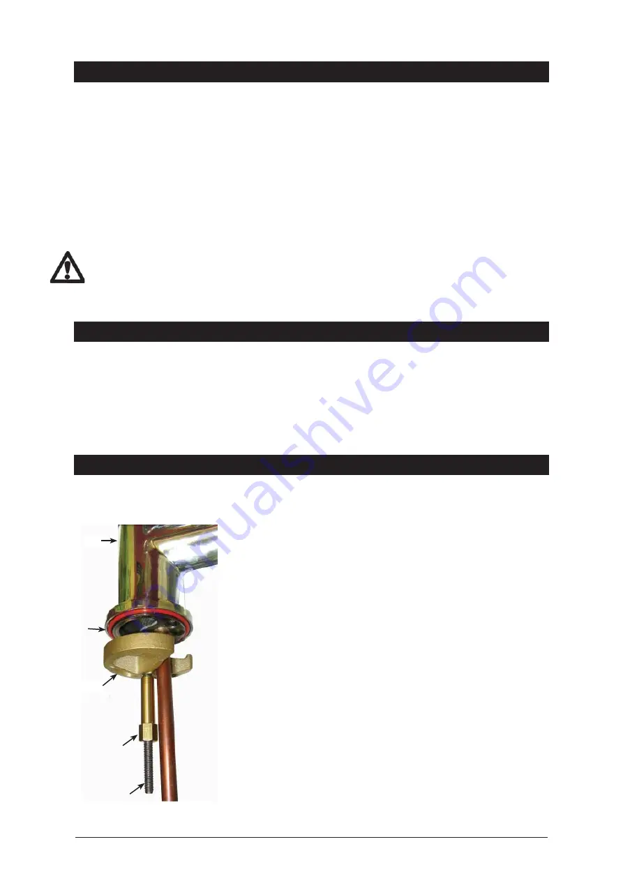
3.   Ensure the silicon O-Ring remains in place as this is the moisture       


seal against the bench / sink top.  

A light smearing of silicon sealant    

on the O-Ring will ensure a watertight fit.

4.   Pass all hoses through the 50mm hole and carefully locate the Head 

Assembly on the bench / sink top.

5.   From the underside of the bench / sink, mount the ‘base block’ by feeding 

each of the tubes and electrical cable evenly in between the legs of the 
‘base block spider’. Slide it up to meet the ‘all thread rod’, and pass the 
‘all thread rod’ through the centre of the ‘base block’.

6.   Hold the ‘all thread’ steady and fit the 6mm ‘fixing nut’ to the ‘all thread’ 

using the tube spanner supplied in the kit. Check the Tap Head position 
before securing it tightly against the bench / sink top. 

NOTE 1: The tap assembly must not be positioned more than 900mm  


above the HydroTap unit.                                                                             
Failure to do this may result in poor water delivery.

NOTE 2: Under no circumstances should the Tap be twisted after the           

installation is complete.

 Installation  procedure

•  Power supply 220-240 Volt AC, for connection to the heater via a 10 amp (160/125) or 15 amp (240/175) GPO.

•  This switch must provide all-pole disconnection and a contact separation of at least 3mm installed in accordance 

with wiring rules.

•  Cold water supply with a minimum working pressure of 200 kPa and a maximum working pressure of 700 kPa 

connected via an isolation valve. If pressure is likely to exceed 700 kPa, install a 500 kPa Pressure Limiting Valve.

•  The fitting of an air flow vent cut into the top half of the cupboard door concealing the HydroTap requiring a cut size 

of approximately 100mm circular, to provide adequate warm air displacement. In installations where high volume  
draw-off will occur, the fitting of the accessory exhaust fan is essential.

Important:  Do not proceed with the installation if these requirements are not met. 

CAUTION:

 In order to avoid a hazard due to the inadvertent resetting of the thermal cut out, this appliance must not 

be supplied through an external switching device, such as a timer, or connected to a circuit that is regularly switched 
on and off by the utility

Installation requirements 

continued

O - Ring seal

Base Block

Fixing nut

Tap

All-thread rod

Summary of Contents for HydroTap All-In-One 89650

Page 1: ...e 1 of 20 Zip HydroTap All In One Filtered Boiling and Chilled water plus Hot and Cold water for kitchens and tea rooms Installation and Operating Instructions This Installation Instruction covers the...

Page 2: ...t details 20 Hydrotap All In One series are able to supply Boiling and Chilled water as well as Hot and Cold water all from the same tap The A series have their Boiling Chilled Hot and Cold outlets co...

Page 3: ...y only if the recommended air gaps are provided these are 65mm min rear clearance and 50mm side clearance An air vent is provided with each unit for high usage applications this must be installed in t...

Page 4: ...o that the connection point and the stop cock will not be obstructed when the undersink unit is installed Installation requirements AV Model 160 Cups of Boiling Water per Hour 125 Glasses of Chilled W...

Page 5: ...t tightly against the bench sink top NOTE 1 The tap assembly must not be positioned more than 900mm above the HydroTap unit Failure to do this may result in poor water delivery NOTE 2 Under no circums...

Page 6: ...xcess force may damage the O rings Check these joints for leaks during initial operation Measure and trim the blue silicon tube and connect it to the chilled water outlet located on the top front righ...

Page 7: ...ovided The following instruction is CRITICAL Adjust both cupboard door hinges and attach the supplied rubber door buffers to the doors to create a 4 mm air gap between the doors and the cupboard This...

Page 8: ...select Exit by pressing ADJUST or to confirm selection and exit model description selection setting 4 The model selection is now complete The Start Filt Flush will be displayed To continue with the fi...

Page 9: ...usable temperature is reached Before using the HydroTap wait 5 minutes after this point to allow adequate fill time The unit is now ready for use Test water delivery from the tap and check for appropr...

Page 10: ...TO TAP 240V GPO NOTE IF THE FLOW RATE IS TOO FAST CUT THE RED SILICONE TUBE 75mm MINIMUM FROM THE BOTTOM OF THE BASE OF THE ALL IN ONE TAP INSERT THE TEFLON RESTRICTOR ABOUT 20mm INTO THE UPPER SEGME...

Page 11: ...65 220 BENCHTOP CABINET DOOR 4mm BUFFER PAD TO ENSURE VENTILATION GAP BRAIDED HOSE BH1 FROM MAINS SUPPLY BRAIDED HOSE BH2 FROM DOMESTIC HOT WATER SUPPLY SILICONE HOSE FROM BOILING WATER TANK IN HYDRO...

Page 12: ...ROM STEAM VENT IN HYDROTAP TO TAP SILICONE HOSE FROM CHILLED WATER TANK IN HYDROTAP UNIT TO TAP BH1 B H 2 B H 3 NOTE IF THE FLOW RATE IS TOO FAST CUT THE RED SILICONE TUBE 75mm MINIMUM FROM THE BOTTOM...

Page 13: ...ALL IN ONE TAP VENTED VERSION MAINS AMBIENT WATER SUPPLY ISOLATION VALVE NOT SUPPLIED 220 65...

Page 14: ...ing slowly The light will flash slowly when the filter is due for replacement and the LCD will show Filter Change Refer to Replacing the filter section of this document Boiling Water Lever Depressing...

Page 15: ...e where shown on the label 7 Avoid touching the filter O rings and filter opening as this may cause bacterial contamination of the cartridge 8 Moisten the O rings with water align the front cartridge...

Page 16: ...ed Press Adjust button to increase Filter Life or Adjust button to decrease Filter Life Filter Life increases in 1000 Ltr increments to a maximum of 10000 Ltrs Reset Litres Filtered This function is t...

Page 17: ...uto Sleep screen Press the Adjust button or Adjust button to select Enable or Disable Only after Enable has been selected can the tap head sensor be calibrated To Calibrate the sensor pull both the HO...

Page 18: ...settings for the maximum dispensing times is 15 secs The ability to change both the Boiling and Chilled dispensing times between 5 and 15 secs in increments of 1 sec is accessible through the Menu sc...

Page 19: ...e Child safety lock see P10 No water flow from mixer tap Faulty non return valve Check and Replace faulty non return valves 3 11 Faulty restrictaflow valve Clean and reset restrictaflow valve item 20...

Page 20: ...37412 AU635979 GB0422305 GB2065848 US4354049 US5103859 and US5099825 Other patents are in force and patent applications are pending As Zip policy is one of continuous product improvement changes to sp...

Reviews: