05
Installation instructions & user manual
804544UK V2.03 Oct 2018 - Zip Econoboil
Technical support
Tel: 0345 6 005 005 Email: [email protected] www.zipwater.co.uk
!
!
Before installation
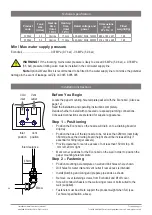
Before installation ensure that provision has been made for the
following
•
Review the technical specifications.
•
Ensure the mounting wall can support the product weight when full of water
(See Technical specification, page 6).
•
Provide sufficient space to install the Econoboil and other components in
accordance with these installation instructions.
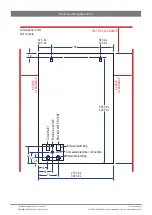
• Position the Econoboil so there is at least 150 mm clearance above it for
service access, 65 mm to its left and 20 mm to its right – the tap nozzle is
usually positioned nominally 360 mm above a draining board, drip tray or sink
bowl area.
•
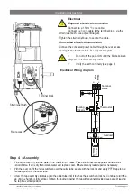
For all Zip Econoboil models, user easy accessible 1 x 230V AC 13A socket or
double pole isolation switch, (correctly rated for the appliance), is required.
•
The Econoboil must be connected in accordance with IEE regulations. See
Technical specification, page 6 for power ratings.
Note
Check cable and plumbing against inlet /outlet positions before proceeding.
•
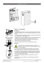
A wholesome (cat 1) water supply connection with isolation valve within
reach of the Econoboil (and positioned so that the isolation valve will not be
obstructed when the Econoboil is installed).
• Vent / outlet drainage to a draining board, drip tray or sink bowl area.
• Access to drainage from a vent situated at the base of the Econoboil.
•
A wholesome (cat 1) cold water supply with a minimum working pressure of:
(see Technical specification, page 6 min. / max. water supply pressure).
•
A 0.35 MPa (3.5 bar) pressure limiting valve supplied must be fitted if the
incoming mains water pressure is likely to exceed 0.5 MPa (5.0 bar).
•
The Econoboil must be placed with its base in a horizontal position.
IMPORTANT!
Do not proceed with the installation if these requirements are not
met.


