StEin
Stationary Equipment Module Page 31
16.
Configuration Example (ZIMO N-Scale Show Layout)
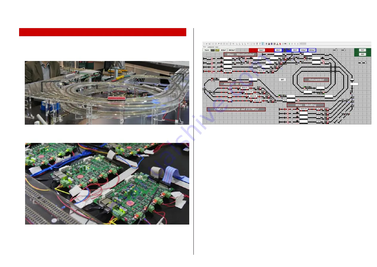
The ZIMO N-scale layout is built on an area of 2 x 1.3 m. The track is mounted directly
on acrylic glass. Since it is a demonstration layout, all (StEin-) modules along with the
wiring are openly installed so they are visible.
There are three stations, two of which are dead-end stations, with a total of 12 tracks,
3 lines under block control and one terminal loop.
The electronic equipment consists of the
ZIMO MX10
central command station
and
(usually)
2 to 3 controllers
and
8 StEin modules
; in the picture some of them with-
out a lid; for the signals there are - at least until 2018 - special signal bridges with in-
tegrated accessory decoders; a later conversion to StEin signal boards is possible.
BTW: This is the state after conversion in 2018; before that, MX8 accessory modules
and MX9 track section modules (9 in total) were used instead of StEin.
The ESTWGJ program (from H.W. Grandjean) is used to control the layout; the inter-
locking panel representation gives a good overview:
Before the StEin modules can actually be configured, that is, the creation of the parameter
sheets (or, as in this case, the single parameter sheet),
the track section divisions and
connection points
, the location of point detectors, switches, uncouplers, and later also the
signals, must be determined.
ZIMO traditionally calls this step
"track section planning"
, because the track sections and
their division are indeed the main focus of considerations and also because they usually de-
termine the number of necessary StEin modules.
On the following page you can see the result of the planning for the N-layout, which is based
on general principles (again mainly concerning the track sections), which are listed below:
Each station track needs at least one section of track isolated on one side (to one of the
track output terminals 1 ... 8). If several trains are to be parked one behind the other,
more sections are needed; However, this is not the case with this layout.
Before the stopping points - at the red signals or bumpers at the end of the track - either
dedicated brake sections connected to separate track section output pins can be installed,
or - much cheaper - point detectors are used (here infrared sensors). In either case, this
forms a stopping distance, starting with the rail gap to the brake section or the point de-
tector and ending with the end of the stop section track. The trains were slowed down al-
ready in the brake section before entering the stop section and so will come to a standstill
at an as exact stopping point as possible.


