Page 4 Track section module MX9
3.
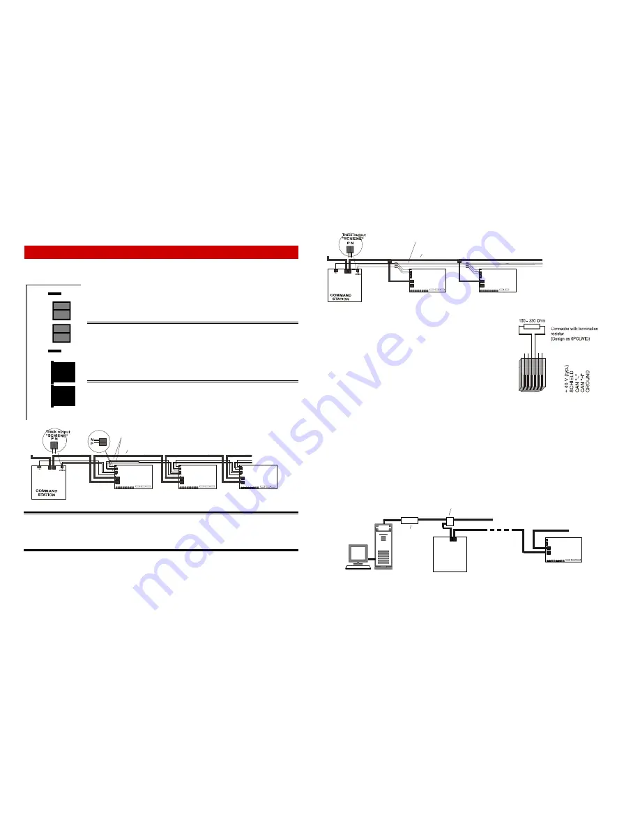
Connecting the MX9 to track power and CAN bus
This chapter applies to all operating modes (except: computer control only in operating mode 3).
The MX9 has two internally-parallel wired connections each to easily connect
it to track power, a common ground and the CAN bus.
The same kind of double-pin sockets are used for the track power hook-up as
are found at the command station, spade terminals for the common ground
and RJ12 sockets for the CAN bus.
ATTENTION:
This chapter describes how the modules are wired permanently to the layout.
However, BEFORE the modules can be mounted and wired as described here, they
each must have their own unique address ranging from 901 to 963.
For this purpose, connect each module separately to the system (command station and
cab) and program it with an address of your choice. See the chapter “Addressing and
programming the MX9“for this procedure.
Once each module (MX9 track section modules, MX8 accessory modules and
possibly other modules) is programmed with its own unique address, it can be
connected permanently to the CAN bus and of course to track power and
common ground as well.
IMPORTANT: The proper pins of the command station’s track output have to be used for connecting the MX9; the
double socket marked “SCHIENE” (meaning main track) with polarity markings “P”, “N”. The polarity “P”, “N”
has to be maintained on all modules! Additionally, an adequate wire size has to be selected for track power and
the common ground wire! In most cases that should be a 1.5 mm
2
(14AWG) wire, smaller N-scale layouts may get
away with a 0.75 mm
2
(22AWG) but large-scale garden layouts need at least 2.5 mm
2
(10AWG) or 4 mm
2
wire.
On larger layouts (10 or more modules), the voltage drop across connectors can be of concern and
daisy-chaining the CAN bus, track power and common ground between modules should be avoided.
It is better to install a bus wire for each and connect small groups of modules to the bus using distri-
bution boxes and the like that are permanently connected with each other (soldered, clamped
etc.).
However, the CAN bus should ALWAYS be of the linear type, which means that there should only
be relative short wires connecting the single MX9’s (or small groups of MX9’s) to the CAN bus (pref-
erably <1m (3ft). Track power and common GROUND, on the other hand, can also be laid out in a
star formation; the main concern here is that the cables are not un-
necessarily long.
Keep track of total CAN bus length! More than 50 m (150ft)?
If the total CAN bus cable length connecting the cabs, track section
modules, accessory modules, turn table modules, infrared modules,
computer and more exceeds 50 m (150 feet), termination resistors
(typically 150 to 330 ohm) should be installed at both ends of the
CAN bus (at an empty CAN bus socket of the first and last compo-
nent) between the pins CAN “H” and CAN “L”. Several hundred me-
ters of CAN bus length are possible with resistors installed. Instead
of making your own resistor–equipped plugs, finished connectors can
also be ordered from ZIMO with part number 6POLWID.
CAUTION, when wiring 110V in close proximity to the layout! 110V wires that run parallel for larger
distances of more than one meter (>3ft) or are bundled together with track wires or CAN bus wires
can cause interference!
COMPUTER connection to the CAN bus
(“Operating mode 3“ – Computer control with STP):
The computer is connected with its serial interface (9-pin) or via USB and the STP CANKey. The
CANKey is connected with a common CAN bus cable to the command station (or any other free CAN
bus socket on the layout). If more connecting capabilities are required than the two sockets of the
MX1 command station, a distributor box like the 6POLTRIP can be used.
2
C
A
N
bu
s
s
o
c
k
ets
2
t
ra
c
k
po
we
r
s
o
c
k
e
ts
N
P
N
P
GROUND
GROUND
CAN
MX1
See chapter 3 regarding the
CAN bus connection to the MX1.
CAN
RS232 or
USB
CAN bus to MX8 and MX9 modules
C
A
N
C
A
N
MX9
CANKey
CAN
from E. Sperrer
(STP developer)
CAN bus to cabs
CAN distributor box, e.g.ZIMO 6POLTRIP
C
A
N
C
A
N
MX9
C
A
N
C
A
N
MX9
C
A
N
C
A
N
MX9
CAN
MX1
C
A
N
C
A
N
C A
N
CAN bus cable, from MX1 to all MX9’s and MX8’s (even in random order)
with RJ 12 connectors at each end (same design as cab cable).
T
o
c
a
b
s
Common GROUND and track power (”SCHIENE”- P, N) - connected from MX1 to MX9’s
M ASS E
C
A
N
MX9
MX9
MX1
C
A
N
C
A
N
CAN bus cable with Mx9’s connected to distribution boxes
T
o
c
a
b
s
Common GROUND and track power “SCHIENE” (P, N) - bus with MX9’s spliced to
distribution boxes
CAN
CAN
MASSE


