Page 2 Track section module MX9
0. About this manual
This instruction manual replaces all previous MX9 manuals. It has been updated and supplemented
in many places to include the “module-autonomous applications” of the MX9 track section mod-
ule.
“Module-autonomous” (“operating mode 1”) means that the logical execution of the functions “stop
in front of a red signal”, “block control” and “hidden station automations” are performed
solely by the MX9, in contrast to a “system-autonomous application”, which is controlled by the
command station MX1 (“operating mode 2”) or by a computer (“operating mode 3”).
Attention: All 4 plug-in sockets must be equipped with the additional ASE conductors for
most “module-autonomous applications”!!
1. Introduction
Track section modules serve to monitor sections of track (with one rail isolated) for
•
Track occupation and
•
Loco number identification (optional)
AND
for the application of “location dependent control” (an international expression summariz-
ing the following functions)
•
track-section
based
“signal controlled speed influence”, as described by the traditional
ZIMO term for speed limit applications F = full speed (no speed limit applied), L = low speed, U
= ultra low speed, H = Halt (stop) and the intermediate steps FL, LU, UH,
•
track-section
based
“ location dependent function control” and the recently introduced
•
transmission of track-section based “position codes” to decoders.
16 track sections, called subsections, can be connected to a MX9 module. 2 subsections are al-
ways paired together and represent one of eight main sections. Speed influence, train number rec-
ognition (if board is installed), function control and position-code transmissions are always carried out
per main section, that is, for both sub sections simultaneously. Occupancy detection on the other
hand is always done independently for each sub section and is a cost-effective and practical ar-
rangement.
The MX9 is suitable for several operating modes, ranging from the simple “stop in front of a red
signal” in “module-autonomous” application to computer control. The MX9 is engineered so that its
hardware (the MX9) as well as the arrangements made on the layout (track sections) can be left in-
tact for the various operating modes. The MX9 is integrated in all cases with the CAN bus network
and communicates with other system components including a computer, if required:
Whatever operating mode the MX9 is supposed to operate in, it has to be connected to track voltage
and the CAN bus. Equally, signals and occupancy indicators can be connected to the MX9 as well as
the loco number identification and display utilized in all operating modes. For this reason, the follow-
ing chapters of this manual are valid for all operating modes:
2. Technical information
3. Connecting the MX9 to track power and CAN bus
4. Addressing and programming the MX9
5. Connecting external occupancy indicators and signals
6. Connecting external switch inputs
7. Loco number recognition and display
The meaning of individual configuration variables (CV’s) however is in part dependent on the operat-
ing mode; therefore they are explained together with the different operating modes in their corre-
sponding chapters:
8. Operating mode 0 (zero)
9. Operating mode 1
10. Operating mode 2
11. Operating mode 3
OPERATING MODE 3: A complete collision avoidance system under computer
control (with STP software), mainly for larger layouts.
OPERATING MODE 2: "System-autonomous applications” for more complex
block control or routing; i.e. ARS (Automated Route Sequences) using bidirec-
tional communication. The ZIMO command station acts as the brain in the sys-
tem in place of a computer. Train movements are defined through sample runs
or cab inputs.
OPERATING MODE 1: "Module-autonomous applications". The logical execu-
tions of routes through a station or block control of a line is the sole responsibil-
ity of the MX9 micro controller, defined by MX9 CV’s. This includes the auto-
matic setting of the appropriate speed limits in both sub-sections in order to
bring a train to a stop in front of a red signal.
OPERATING MODE 0 (zero): Direct speed limit assignments to each of the 8
main sections of the MX9; fixed settings through MX9 CV’s or selectable via
cab.
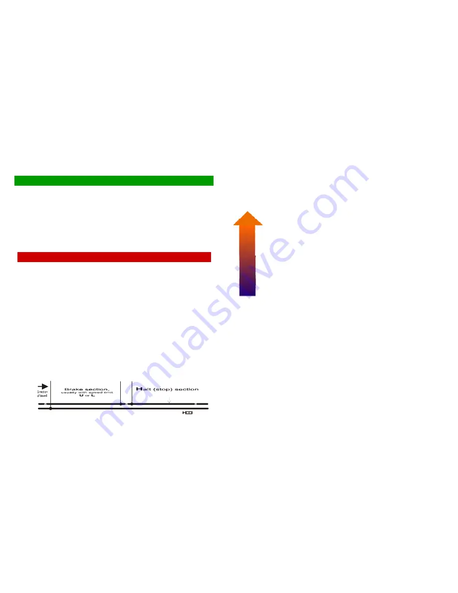
Desired stop point
Typical signal location
Safety margin
Specified
stopping distance
Isolated track sections; connected to one
MX9 main section e.g. 1A &1B.
Typical section arrangements for
“Stop in front of a red signal” or a station siding.
Common rail connected to “N” pin
at command station’s track output.


