background image

12

10.2.4 Sensing: Piston position, magnetic

3


Remove the mounting screws.


Remove the cover.


Insert the pre-assembled assembly for 

sensing. 


Mount the assembly with the provided 

screws.

3

Piston position sensor, magnetic 

ZUB1098XX

INFORMATION


More information can be found in the installation and operating instructions of MFS01-S-KHC-P2-PNP.

10.3 Installing the energy supply


Apply the pneumatic fittings lightly.

9


Align the pneumatic fittings.


Tighten the mounting screws.

9

Pneumatic fitting

INSTALLATION AND OPERATING INSTRUCTIONS:

XYR

DDOC00257 / d

EN / 2022-05-09

Zimmer GmbH • Im Salmenkopf 5 • 

 77866 Rheinau, Germany • 

 +49 7844 9138 0 • www.zimmer-group.com

Summary of Contents for XYR Series

Page 1: ...INSTALLATION AND OPERATING INSTRUCTIONS Axis compensation module pneumatic XYR series DDOC00257 THE KNOW HOW FACTORY www zimmer group com...

Page 2: ......

Page 3: ...ing inductive 11 10 2 2 Sensing Eccentric clamp inductive 11 10 2 3 Sensing No pressure 11 10 2 4 Sensing Piston position magnetic 12 10 3 Installing the energy supply 12 10 4 Flow chart of pneumatic...

Page 4: ...iding these dangers The warning symbols are assigned according to the type of danger WARNING This notice warns of a situation that is potentially hazardous to personal health Ignoring these notices ca...

Page 5: ...in the following examples require the written permission of the manufacturer Use of the product under extreme conditions such as aggressive fluids or abrasive dusts Additional drilled holes or threads...

Page 6: ...of 8 bar The product is designated for use in closed facilities Direct contact with perishable goods food is not permitted 4 Personnel qualification Installation commissioning and maintenance may only...

Page 7: ...ordable installation sizes Using adjustment screws the properties of the product can be optimally adapted to your application Depending on the requirement the compensation plates can be locked centric...

Page 8: ...nsport to ensure that no unexpected movements can occur Before commissioning the product and after transport check all power and communication connections as well as all mechanical connections If the...

Page 9: ...y residual energy that may be present NOTICE Installation may only be carried out by qualified personnel in accordance with these installation and operating instructions Switch off the power supply be...

Page 10: ...with the mounting screws To tighten the mounting screws there are threaded holes on the underside of the product Align the axis compensation module centrically 7 Mounting screw 8 Straight pin not incl...

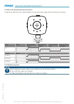
Page 11: ...for sensing are included in the scope of delivery 1 Locking sensing inductive 2 Eccentric clamp sensing inductive 3 Piston position sensor magnetic ZUB1098XX 1 2 3 2 10 2 1 Sensing Locking inductive...

Page 12: ...XX INFORMATION More information can be found in the installation and operating instructions of MFS01 S KHC P2 PNP 10 3 Installing the energy supply Apply the pneumatic fittings lightly 9 Align the pne...

Page 13: ...lamp deactivated 1 0 a 0 b Sensors Status Sensing 1 1 0 Sensing 2 1 0 Sensing 3 Q1 Q2 10 5 Installing accessories NOTICE Before installing an accessory make sure it is suitable for use with the select...

Page 14: ...stroke Secure the setting by tightening the hexagon head 10 6 2 Setting the compensation force INFORMATION To set the compensation force release the hexagon head until the hexagon socket can be turne...

Page 15: ...use that does not comply with the power specifications Permissible temperature range not observed Even though the product is maintenance free as mentioned above perform a regular visual inspection to...

Page 16: ...he specific technical documents were produced in accordance with Annex VII Part B of this Directive We undertake to provide the market supervisory bodies with electronic versions of special documents...

Reviews: