INSTALLATION AND OPERATING INSTRUCTIONS:
Tool changer, pneumatic, WWR1000 series
Zimmer GmbH
●
Im Salmenkopf 5
●
77866 Rheinau, Germany
●
Phone: +49 7844 9138-0
●
Fax: +49 7844 9138-80
●
www.zimmer-group.de
7
DDOC00291 / 0
EN / 2018-09-1
1
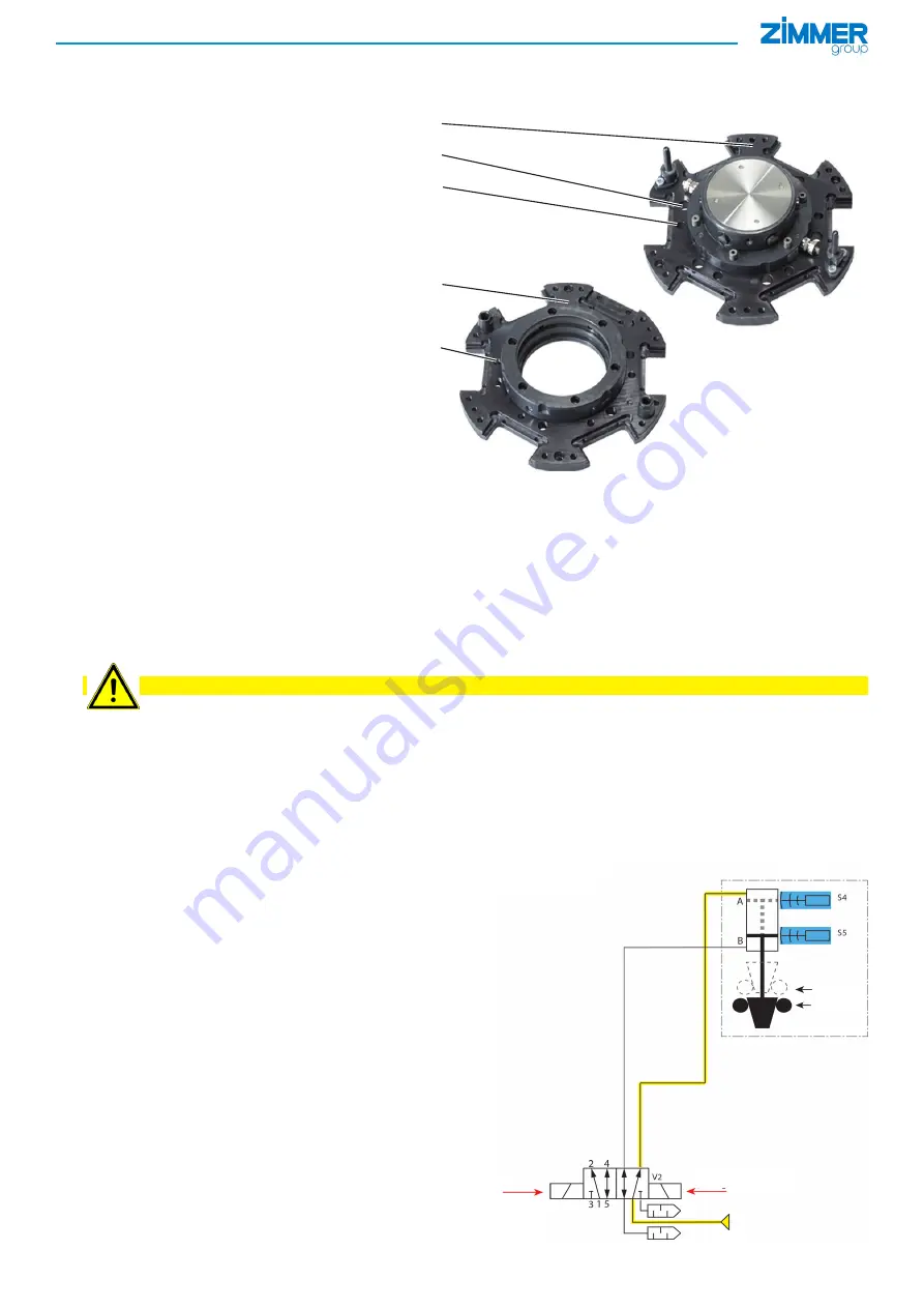
Fixed part
9
:
► Installation of the fixed part with
hexagon socket cylinder screws
bn
in
accordance with DIN912 or ISO4762,
strength class 8.8.
► Insert the fixed part
9
against the
handling system, with the help of the
straight pins
bo
and the centering
diameter on the robot flange.
►
The screw-in depth must be at least
1,5 times the diameter.
►
Observe the permitted tightening
torque – see table.
Loose part
bp
:
►
Installation of the loose part using
cylinder screws
bn
(strength class 8.8).
►
The loose part
bp
is positioned on the
tool by means of the straight pins
bo
and the tapped hole
bq
.
►
The screw-in depth of 17 mm into the
loose part must be observed
depending on model.
►
Observe the permitted tightening
torque – see table.
6.2 Checking operational readiness
After the element has been properly installed, check whether it is ready to be operated according to the following
characteristics:
►
Look and listen for leaks in the pneumatic connections.
►
Check all mounting screws for their prescribed tightening torque.
►
Look and listen for leaks in the pressurized element.
►
Check to make sure the element is functioning properly by opening and closing it manually.
CAUTION: Ensure that the loose part is not accidentally ejected!
7 Pneumatic connection
The pneumatic connection of the tool changer always takes place at the connections 9 of the fixed part.
►
Air connection A: locked.
►
Air connection B: unlocked.
The following is a description of two possibilities for operating the element in accordance with the rules of the DIN EN
ISO 13849-1 standard in different control categories, allowing the required performance level (PL) to be reached:
7.1 Control category 1
• Proven components
• Zero defect detection
• PL c accessible
The element is controlled via a 5/2-directional valve.
To implement the safety function, the use of “proven
components,” as described in Chapter 6.2.4 of the
EN ISO 13849-1, is sufficient.
A simple final position control is possible with the S4
and S5 inductive proximity switches directly at the tool
changer (see accessories).
9
bn
bo
bp
bq
Unlocked
Locked
Control signal
“locked”
Control
signal
“unlocked”
WWR
Position “locked”


