


Handbook
Ucontrol
type-lines PXDM
Date 06/04
TBL02_55-GB06/04
Part.-No. 00153239-GB
Page 15 / 105
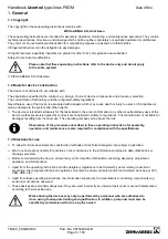
5.5 Motor protection
¨
The motor can be protected by connecting the thermal contacts or PTC resistor.
¡
When several motors are connected ensure that the thermal contacts or PTC
resistors are always connected in series. A maximum of six individual thermistors
(DIN 44081 or DIN 44082) may be connected in series to a single device. Depending
on the motor type, at least two or three individual sensors are built in.
¡
Monitoring of motors in “Ex“ zones is not permissible. For systems of this type, an
additional posistor tripping unit is required, with disconnection via a separate motor
protection circuit.
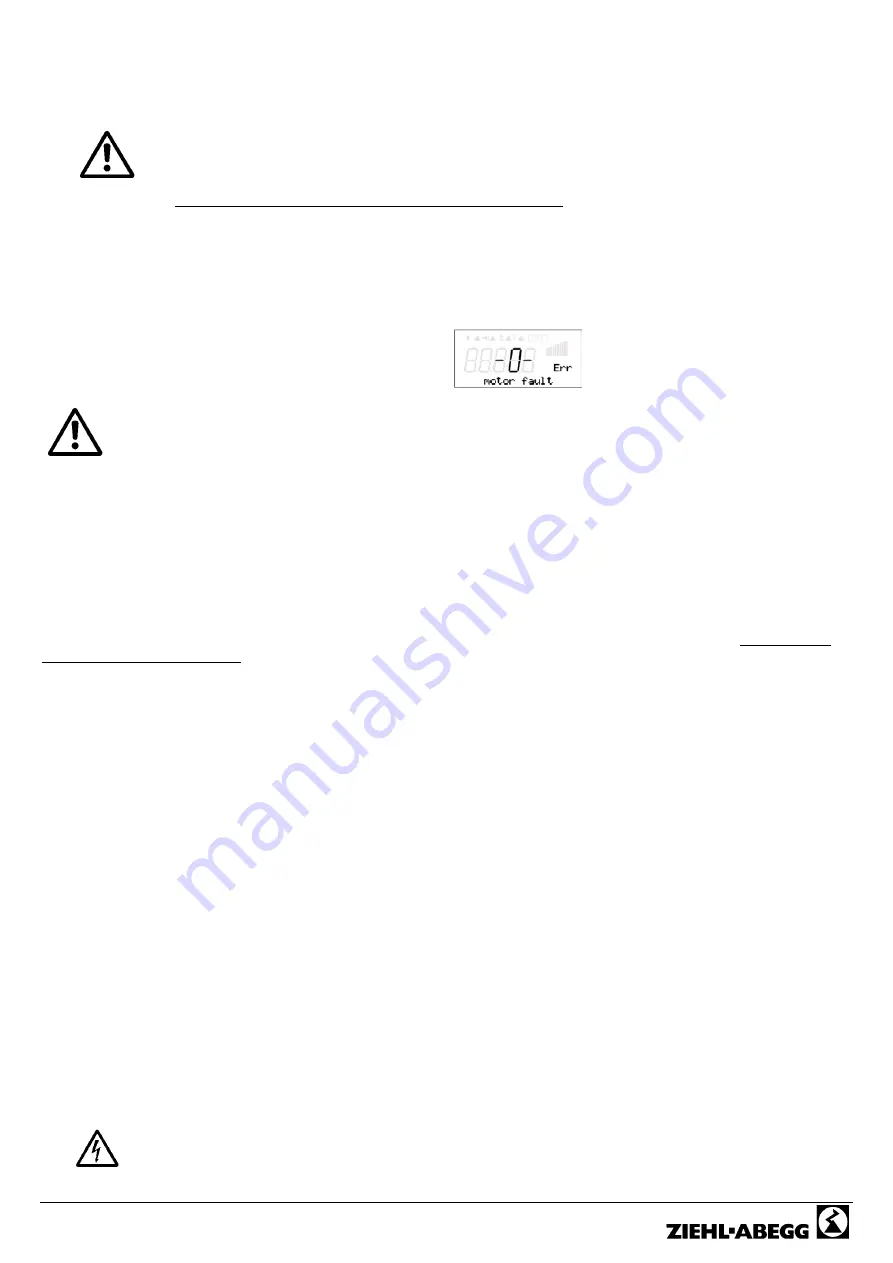
The unit switches off when a connected thermal contact or PTC resistor has tripped the circuit (interruption between both
TK terminals). The unit then remains switched off. A programmed fault-indicating relay is triggering,the internal red LED
for motor fault illuminates, the green LED for operating goes off. The unit starts up again once the drive has cooled down
by switching the mains voltage OFF and then ON again or by enable ON/OFF (
F
IO Setup).
Display during motor fault alternating to the actual value
¡
An outside voltage may never be connected to the terminals “TK”!
¡
The internal motor protection does not function if a bypass circuit has been realised.
In this case and as well as other precautions, an additional thermal contact
protective device is necessary.
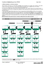
5.6 Signal connection to analog inputs (Analog IN1, Analog IN2, ..)
The unit has 2-analog inputs
Input 1 (Analog IN1) terminals „E1“ and „GND“
Input 2 (Analog IN2) terminals „E2“ and „GND“
Ensure correct polarity when connecting; a 24 V DC power supply is integrated for sensors. For sensors in two-wire-
technology (4-20 mA signal), the connection is made on the +24 V and „E1“ or „E2“ terminals (the GND terminal is
omitted).
The connection is independent of the programmed operating mode and from the sensor signal employed (
F
Presets of
the selected operating mode).
5.7 Output voltage 0-10V (Analog OUT)
The 0-10 V analog outputs can be allocated with various functions
(
F
IO Setup: Analog output A). Connection to terminal „A“ - „GND“ = Analog OUT (I
max
10 mA)
5.8 Voltage supply for external devices (+24 V, GND)
A voltage supply is integrated for external devices, e.g., for a sensor.
Terminal
+24 V Output voltage tolerance
±
20 %.
Max. load current 120 mA (for connection to an external AXG terminal minus ca. 50 mA)
During an overload or short-circuit (24 V
«
GND), the control voltage (and thus the controller) is disconnected (Multifuse).
Automatic start after elimination of the cause of error
5.9 Relay outputs (K1, K2)
Various functions can be allocated to the relay outputs K1 and K2
(
F
IO Setup: Function and inversion of the relay outputs). Max. contact load 5A / 250 V AC
Connection of the floating contacts of relay K1 to the terminals 11, 14, 12
Connection of the floating contacts of relay K2 to the terminals 21, 24, 22
5.10 Digital inputs (D1, D2)
Various functions can be allocated to the digital inputs D1 and D2
(
F
IO Setup: Functions summary of the digital inputs).
Activation via floating contacts (a low voltage of ca. 24 V DC is connected).
Never apply external voltage to the digital inputs!
Summary of Contents for Ucontrol PXDM Series
Page 80: ...Handbook Ucontrol type lines PXDM Date 06 04 TBL02_55 GB06 04 Part No 00153239 GB Page 80 105 ...
Page 92: ...Handbook Ucontrol type lines PXDM Date 06 04 TBL02_55 GB06 04 Part No 00153239 GB Page 92 105 ...
Page 96: ...Handbook Ucontrol type lines PXDM Date 06 04 TBL02_55 GB06 04 Part No 00153239 GB Page 96 105 ...
Page 100: ......


