


Handbook
Ucontrol
type-lines PXDM
Date 06/04
TBL02_55-GB06/04
Part.-No. 00153239-GB
Page 12 / 105
4.5 Potential at control voltage connections
The control voltage connections (<50 V) relate to the joint GND potential (Exception: Relay contacts are potential free).
There is a potential separation
between the control voltage connections and the earthed conductor.
It must be ensured that the maximum external voltage at the control voltage connections cannot exceed 50V
(between “GND” terminals and “PE” earthed conductor).
If necessary, a connection to the earthed conductor potential can be established, install bridge between “GND“ terminal
and the “PE“ connection (terminal for screening ).
4.6 Radiating interference / cable installation
Motor feeder cable
The applicable standard for radiating interference is EN 50081.
A unshielded motor feeder cable is required for compliance with the standard.
Sensor cable
Screened control cables must be used to prevent parasitics when the cable length is longer than 20 m or when routed in
the immediate vicinity of other cables (e.g. installed in a cable duct). When using a screened cable, the screen must be
connected to the protective conductor at one end, i.e. only at the control unit (as short and of as low an inductance as
possible!). The sensor cables may not be longer than 30 m (screened)!
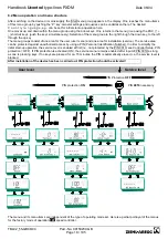
4.7 Electrical installations
¡
Electrical installations may only be carried out by trained specialists in accordance
with general and locally applicable regulations!
¡
Dangerous electric voltages are exposed when the controller is opened. Behave
accordingly when installing the device and ensure that employees without
appropriate training cannot enter the hazardous area!
The relevant connections can be found in the circuit diagram enclosed in the enclosure
appended to these operating instructions (
F
Enclosure: Connection diagram)!
Only cut off necessary cable inlets respectively to the cable diameter (depending on the housing model)!
When using “WAGO” terminal strips, insert only one conductor with max. 2.5
¨
.
Cable sleeves must be used for stranded leads!
The housing must be correctly screwed into position before final
commissioning is performed and any cable ducts openings not used
(depending on the housing model) must be sealed using the supplied stoppers!
Summary of Contents for Ucontrol PXDM Series
Page 80: ...Handbook Ucontrol type lines PXDM Date 06 04 TBL02_55 GB06 04 Part No 00153239 GB Page 80 105 ...
Page 92: ...Handbook Ucontrol type lines PXDM Date 06 04 TBL02_55 GB06 04 Part No 00153239 GB Page 92 105 ...
Page 96: ...Handbook Ucontrol type lines PXDM Date 06 04 TBL02_55 GB06 04 Part No 00153239 GB Page 96 105 ...
Page 100: ......


