


ZERO EMISSION VEHICLES AUSTRALIA
8-16 CELL LITHIUM BATTERY MANAGEMENT SYSTEM
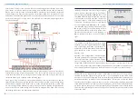
Shunt size
None, 100,
200 or 500A
Selects the size of current shunt connected to
the BMS’s shunt interface terminals, for correct
current scaling. (75mV shunts only.)
This should be set to “None” if you have no
shunt connected, or are using an external
current sensor on the CAN bus.
Min voltage
1.50-4.00V
The minimum voltage any single cell should
be allowed to reach. If any cell goes below
this threshold, the LV output relay will go open
circuit.
Max voltage
2.00-4.50V
The maximum voltage any single cell should
be allowed to reach. If any cell goes above this
threshold, the HV output relay will go open
circuit.
Balance voltage
2.00-4.50V,
Dynamic
or Off
The voltage threshold where shunt balancing will
occur. Balancing should only be performed on
cells which are higher than average, so typically
set this to the average maximum charge voltage
of each cell (i.e max charge voltage divided by
number of cells).
Set to 4.51V for dynamic balance voltage or
4.52V for Off.
BMS hysteresis
0.00-0.50V
Applies to Stationary Mode only.
Adds hysteresis
to min/max voltage reset thresholds, so that
charge and load relays are not switched on and
off too rapidly. For example, after an under-
voltage trip, the LV relay won’t be re-enabled
until the cell recovers to 0.2V above Min
Voltage.
BMS min temp
-41C to 100C The minimum allowable temperature for
the battery pack. If a temperature below
this threshold is detected, a warning will be
generated and charging will be disabled.
Set to -41C to disable (will show as “Off”)
BMS max temp
0-101C
The maximum allowable temperature for
the battery pack. If a temperature above
this threshold is detected, a warning will be
generated and chargers and loads will both be
disabled.
Set to 101C to disable (will show as “Off”)
Charger voltage
0-70V
For CAN integration with TC Chargers or SMA/
Goodwe inverters only.
The maximum voltage that the BMS will instruct
the charger/inverter to reach.
Charger current
0-100A
For CAN integration with TC Chargers or SMA/
Goodwe inverters only.
The maximum current that the BMS will instruct
the charger/inverter to reach.
Stationary mode
No/Yes
Whether the BMS behaviour should be set for
stationary applications. Please see “Stationary
Mode” section for further explanation.
Reverse current display
No/Yes
By default, the BMS16 displays discharge amps
as positive / charge amps negative. If preferred,
you can reverse the display so that discharge
amps are negative / charge amps are positive.
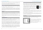
Night Brightness
0-100%
Adjusts the brightness of the LCD display in
low light mode, to reduce screen glare at
night. Toggle between full brightness and night
brightness by swiping a finger up/down.
Buzzer On
Yes/No
Selects whether the Monitor should sound the
buzzer for alerts. (Safest to leave this on.)
Use Fahrenheit
Yes/No
Changes display of temperature units to
Fahrenheit instead of Celcius.
SoC Display
Percent or
Amp-Hours
The battery State of Charge value displayed on
the Monitor can either be shown as a percentage
of full charge, or as the number of amp-hours
remaining.
9
10


