


ZERO EMISSION VEHICLES AUSTRALIA
8-16 CELL LITHIUM BATTERY MANAGEMENT SYSTEM
Ensure that all wiring is secured so it will not become damaged from vibration or abrasion.
Small fuses (~1A) may be used to protect wiring, best installed close to each cell terminal.
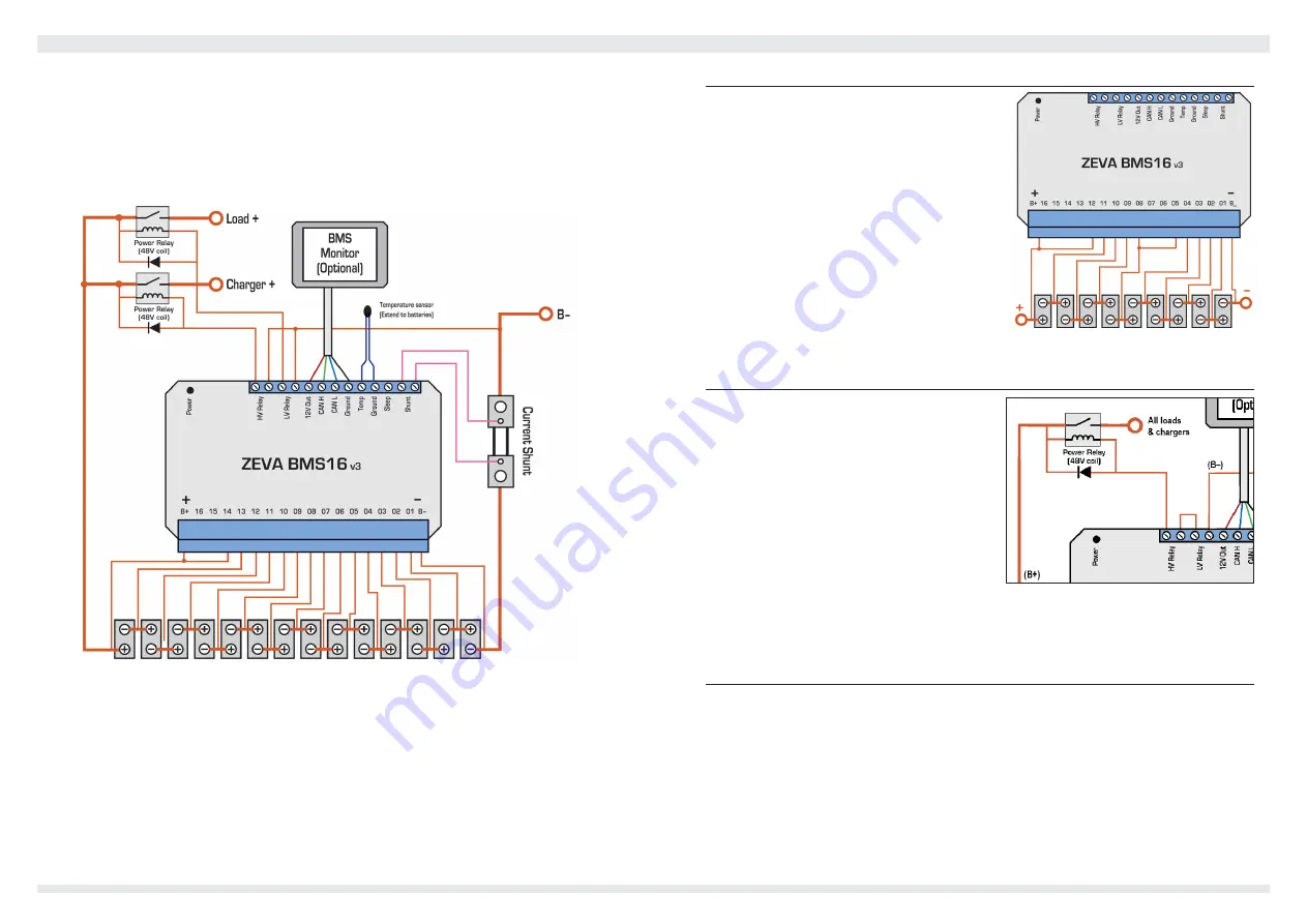
Device power is always taken from terminal B+. To provide power to the BMS, simply add
a short jumper wire from your most positive cell terminal to B+. (You can optionally run a
dedicated wire from battery positive to B+ to avoid voltage measurement errors on your most
positive cell, though it is usually only a few millivolts.) An example wiring diagram for 14
cells is shown below.
Relay outputs are floating / isolated, and have a maximum rating of 70V and 1A continuous.
In installations with a single “battery enable” relay, the LV and HV relays may be wired in
series such that either an over-voltage or under-voltage condition will open the relay to
isolate the battery pack as shown on the following page.
Once your wiring is complete, press the power button on the top left of the case, and the
status LED should come on. A green light indicates all cells are within correct voltage range,
and both relay outputs will be closed circuit. A steady red light indicates one or more cells
are over-voltage, and the HV Relay outputs will be open circuit. A blinking red light indicates
one or more cells are under-voltage, and the LV Relay outputs will be open circuit. Green/
red flashing indicates an over-temperature shutdown.
Packs Smaller Than 12 Cells
Internally the BMS16 uses two voltage sampling
chips which are connected to up to 8 cells each,
one spanning terminals B– to 08 and the second
from 08 to 16. These samplers require a minimum
of 4 cells each for reliable operation, so for packs
with fewer than 12 cells, some unusual wiring
is required. The most positive four cells should
be connected between 08 to 12, with a jumper
from 12 to B+ (since the BMS draws power from
B+ to power itself). Then the remaining cells are
connected from B– up, with a wire jumper from
the most positive terminal in this group up to
08. An example case for a 9-cell pack is shown
right.
Protection Using a Single Contactor
It is possible for the BMS to control a single
contactor to protect against both under-voltage
and over-voltage conditions concurrently. To
achieve this, the HV Relay and LV Relay terminal
pairs should be wired in series, as per the
diagram, right.
Note that in this configuration, if the BMS opens
the main contactor due to an under-voltage cell
for example, the battery pack will also be isolated
from any charging sources so will be unable to
charge (and correct the under-voltage condition) until the system is reset manually. For this
reason it is important in this case that BMS intervention is an exceptional circumstance, and
under normal operation chargers and loads will not cause any cells to exceed safe range.
Current Shunt
The BMS16 may be supplied with either a 100A, 200A or 500A shunt. The shunt may be
installed at either the negative end, positive end, or even somewhere in the middle of the
battery pack. The shunt is connected via two wires to the associated terminals on the BMS16.
For best performance, twisted pair wire is recommended. The sample wire from the anode
/ positive side of the shunt (closest to the +ve terminal of the battery) should be connected
to the left-hand terminal (as shown on the wiring diagram, left). By default, discharge amps
are shown positive, though this can be reversed in settings if preferred. If your polarity seems
to be reversed (e.g discharge current is causing SoC to increase), simply swap the two shunt
wires at the BMS.
3
4


