


ZERO EMISSION VEHICLES AUSTRALIA
8-16 CELL LITHIUM BATTERY MANAGEMENT SYSTEM
The BMS stores calibration for the shunt zero point in memory. If the current displayed is not
zero when it should be, you can tap and hold to bring up Options buttons, then tap Zero
Current (while no current is flowing) to recalibrate the zero point.
Temperature Sensing
A temperature sensor may be connected to the BMS16 between the Temp and Ground inputs.
The scaling is calibrated for a 100Kohm NTC thermistor with B25/100 value of 4540K. These
are available from us, or many large electronics vendors.
It is recommended that the temperature sensor is installed somewhere near the middle of the
pack, since this is typically the warmest location. Wires on the sensor may be extended as
long as necessary. Temperature limits may be adjusted in settings, to warn if the temperature
exceeds safe range, restrict charging if the battery is too cold, or shut everything down if the
battery gets too hot.
Sleep Mode
The BMS16 has a Sleep terminal which may be used to put the device into a lower power
standby mode by connecting a wire from it to a Ground terminal. It is most commonly
used in mobile applications, for when a vehicle is neither being driven or being charged.
(Stationary applications typically run 24/7 so the Sleep terminal is often unused.)
Sleep mode will shut down the CAN bus and turn off both relay outputs. The device continues
to monitor cell voltages and shunt current, and will turn itself off completely if any cells get
extremely low.
Automatic Pack balancing
In battery packs built from many cells, optimum performance is attained when all cells are at
the same State of Charge, also known as pack balance. The BMS16 uses a system known as
“shunt balancing”, which switches on resistors across any cells which are above a threshold
voltage to reduce their charge and bring them into line with other cells.
By default the BMS16 uses a dynamic balance threshold, where any cells more than 0.01V
above the average receive balancing. The threshold may also be set manually – if so it is
best to set it to the average maximum charge voltage, so that only cells above average at the
end of a charge receive balancing. Manually setting a shunt threshold below the maximum
charge voltage is not recommended since it may result in all balancers running concurrently,
which actually negates the effect and generates extra heat. Balancing can also be disabled.
The shunt balancers are quite small and can take a long time to correct large imbalances. If
possible it is recommended to manually balance your cells prior to initial pack assembly (e.g
by charging each cell individually, or wiring them all together in parallel to equalise with each
other). However the shunts will get an unbalanced pack incrementally closer to balanced each
charge, and once balanced are able to maintain balance with minimal effort.
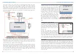
CAN Bus Wiring
The BMS16 has four screw terminals for connecting CAN bus wiring: 12V Out, CAN H,
CAN L and Ground. The monitor CAN plug uses a Molex Eurostyle screw terminal. These
connectors require some force to plug in, so make sure the plug is fully inserted for a reliable
connection. Wiring for the Eurostyle connector is shown right.
Wire gauge around 16-24AWG is recommended for appropriate
current rating and mechanical strength. For best noise immunity
in high EMI environments, shielded twisted pair cable is
recommended, with two conductor pairs – one pair for CAN
signals, and one pair for bus power. The shield can be connected
to the Ground terminal at the BMS. We use and recommend
Belden 8723 wire, or equivalent.
For optimum performance, CAN buses should be wired as a single daisy chain of devices
(without branching), and terminated at both ends of the bus with a 120Ω resistor across the
CAN H and CAN L lines. The monitor includes termination resistor built-in. The CAN bus is
galvanically isolated from the main battery pack.
The 12V Out terminal is limited to 200mA current and is primarily intended for powering CAN
devices such as a monitor and/or CAN current sensor, but may also be used to power other
small 12V devices such as solid state relays.
BMS16 Monitor
The BMS16 Monitor is an optional colour touchscreen which may be used to remotely
interact with the BMS16. The Monitor displays various pages of information:
BMS Status: Running
Voltage
Current
Power
Temp SoC
23˚C 90%
48.5V
12.3A
0.6kW
The BMS Status page is the standard display when
the system is running, showing pack voltage, current,
power, temperature, battery state of charge. This will
only be shown if a current sensor is present.
Tapping the panel on the left or right side will toggle
between the different display pages.
5
6
Shield
Ground
CAN L
CAN H
12VDC


