background image

109

HYDRAULIC SYSTEM

F_02_H15

F_02_71

F_02_124

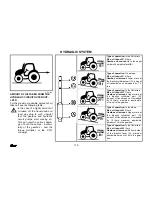
CONTROL PANEL LOCATION - HYD-
RAULIC WITH MECHANICAL CON-
TROL SYSTEM

Electro-hydraulic control panel (1) is lo-
cated on the upper part of right fender.
Description of hydraulic control is men-
tioned in chapter – hydraulic with me-
chanical control systém

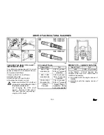
OUTER HYDRAULIC CIRCUIT

It supplies pressure oil for the hydraulic
appliances connected to the outer out-
lets of the hydraulic system fitted with
quick couplers. The rear and front quick
coupler plugs (A and B respectively) in-
ner diameter is 12,5 mm and they com-
ply with the international ISO 5675 stan-
dard.

QUICK COUPLERS COUPLING AND
UNCOUPLING

When coupling and uncoupling the
quick couplers be very careful be-
cause of the residual oil, which
remains in the socket or in the
plug of the quick coupler.
For the ecological reasons this
residual oil has to be removed
with any cloth after each un-
coupling of the quick couplers.

Summary of Contents for 86 41 forterra turbo

Page 1: ......

Page 2: ......

Page 3: ...f operation We are sure that you will find many pieces of new and useful information and you will get a perfect overview of the methods you can apply for the best utilization of our product for the mo...

Page 4: ...4 The specified technical data design outfit material and visual aspects are in force at the moment of impression The manufac turer reserves the right to modifications...

Page 5: ...41 Forterra Page Location of the serial numbers Z 8641 Z 9641 Z 10641 Z 11441 7 Location of the serial numbers Z 11741 8 Safety hints for the user 10 Preventive daily maintenance 14 Survey of the trac...

Page 6: ...Z 8641 Z 9641 Z 10641 Z 11441 Z 11741 Zetor 8641 Forterra turbo 60 kW Zetor 9641 Forterra turbo 66 kW Zetor 10641 Forterra turbo 74 kW Zetor 11441 Forterra turbo 81 kW Zetor 11741 Forterra turbo 88 k...

Page 7: ...7 LOCATION OF SERIAL NUMBERS Z 8641 Z 9641 Z 10641 Z 11441 F_02_154...

Page 8: ...8 LOCATION OF SERIAL NUMBERS Z 11741 F_02_187a...

Page 9: ...the following frames Tractor type ZETOR 8641 ZETOR 9641 ZETOR 10641 ZETOR 11441 ZETOR 11741 The terms to the right to the left at the front and at the rear refer to the direc tion of the tractor move...

Page 10: ...ay not be subjects of claims GENERAL SAFETY REGULATIONS 1 Operation of the tractor may only be entrusted to a trained in operator per fectly acquainted with operating and safety rules and possessing v...

Page 11: ...suspended at the front three point hitches reduce the tractor travel speed to 20 km h 23 When combining the Z 8641 Z 11741 tractors with the machines and implements of high hauling resistance when th...

Page 12: ...d do not moke 45 When checking the storage battery electrolyte for proper level do not smoke nor use the naked flames 46 In the environments of enhanced danger of fire haylofts straw heaps and the lik...

Page 13: ...result in serious injury of some tissues 57 The air conditioning system is fitted with quick couplers which allow sepa rate the cab from the tractor body if nec essary without any leak of the coolant...

Page 14: ...14 PREVENTIVE DAILY MAINTENANCE To be carried out daily or at the latest after every 8 to 10 operating hours F_02_148...

Page 15: ...ng the oil dipstick check the oil for level and the engine lubrication system connections for tightness Keep the oil level between the dipstick marks COOLING SYSTEM Check the engine cooling system con...

Page 16: ...hin the limits of 3 4 maxi mum level and 1 2 minimum level tank capacity TRAILER PNEUMATIC BRAKES Check the pneumatic brake system for tightness and the tractor brake with trailer efficiency For detai...

Page 17: ...ts clogging with impurities The sensor makes switch on a signal light installed in the dashboard in case the air cleaner is heavily obstructed CAB FILTRATION Check and clean if necessary the cab venti...

Page 18: ...air conditioning condenser to the left hand tractor side Clean the front part of engine radiator air conditioning condenser by means of pressured air blow air in direction from the engine Remove the r...

Page 19: ...2a SHORT TEST FOR PROPER FUNCTION On starting the engine make sure the engine lubrication signal light if off as well as the light of proper electrical charging and check the steering hydrau lic circu...

Page 20: ...20 NOTE...

Page 21: ...ent 27 Vertical seat adjustment 27 Grammer Driver s seat 28 Adjusting the seat to the driver s weight 28 Longitudinal adjustment 28 Tilting steering wheel 29 Angular adjustment 29 Vertical adjustment...

Page 22: ...Z 11441 43 Engine run stop controller Z 8641 Z 11441 43 Pedals and levers 44 Main gearshift lever and reverse march shift lever 44 Road and reduced gear shift lever 44 P T O shaft dependent and indepe...

Page 23: ...lever and the hand operated fuel supply lever The safety cab is normally fitted with toned glasses OPENING THE DOOR FROM OUTSIDE The cab door can be locked with key from outside OPENING THE DOOR FROM...

Page 24: ...e implements sus pended at the tractor rear three point hitch make sure that no collision with the open rear win dow and the fully raised hitch is imminent If so operation with closed window is recomm...

Page 25: ...maximum WASHER TANK The washer tank is installed at the cab rear wall from outside WASHER CONTROL The windscreen washer initiates its op eration on depressing the front two speed wiper changeover swit...

Page 26: ...raveler s seat may be tilted up STOWING COMPARTMENT AND TOOL BOX The stowing compartment is placed at the L H side of the driver s seat The toolbox is installed in the rear part of the cab behind the...

Page 27: ...The weight set up appears in the seat rear cover recess The sprung stroke equals 120 mm While driving do not adjust the seat because of the risk of acci dent LONGITUDINAL SEAT ADJUSTMENT Longitudinall...

Page 28: ...r can be furnished with the seat Grammer ADJUSTING THE SEAT TO THE DRIVER S WEIGHT For the adjustment turn the plastic ro sette installed at the front part of the seat console LONGITUDINAL ADJUSTMENT...

Page 29: ...teering wheel position both in angle and the height The two functions are controlled with a single lever only ANGULAR ADJUSTMENT The angular setting provides 10 posi tions spaced at 4 within the limit...

Page 30: ...HEATING VALVE CONTROLLER A a Heating valve closed b Heating valve open FAN CONTROLLER B 0 Fan switched OFF 1 Fan low speed 2 Fan medium speed 3 Fan maximum speed SWITCH AIR CONDITIONING C For switchin...

Page 31: ...controller in this position for the indispensable period of time only HEATING AND AIR CONDITIONING SYSTEM PROPER OPERATION For the heating of air conditioning proper operation certain overpressure has...

Page 32: ...r of the cab by the operator may take place Such a situation may result in sensation of fatigue Note For the work set the controller D to a position between a and b in ac cordance with the individuall...

Page 33: ...B To ensure a quick windscreen defrosting aim the middle heating breathers 3 un der an angle of approximately 45 at the windscreen Aim the side breathers 4 under an angle of approximately 45 at the ca...

Page 34: ...34 TRACTOR SURVEY B21a...

Page 35: ...ttery charging red ON in case the charging system has failed 8 Lubrication red ON when the en gine oil pressure decays below 120 to 60 kPa 9 Air cleaner clogging yellow ON if the air cleaner is obstru...

Page 36: ...36 TRACTOR SURVEY F54b...

Page 37: ...al in strument dashboard is identical to the analog dashboard 21 Pushbutton of the enginhours Data shown on the display 22 Battery voltage pushbutton Data on the voltage in volts will be displayed wit...

Page 38: ...mp activation is signaled with the symbol illuminated on the on the changeover switch e Warning lamp switch f Front driving wheel switch The en gagement of the front driving wheel is signaled with the...

Page 39: ...driving axle in case the rear wheels slip in order to increase the tractor towing ca pacity a Front driving axle disengaged b Front driving axle engaged In the tractor put out of operation tractor be...

Page 40: ...ential lock disengaged b Differential lock engaged To engage the lock depress the push button which when released recu perates its basic position The differential lock engagement is sig naled with the...

Page 41: ...le panel be neath the instrument dashboard KEY IN THE 0 POSITION Voltage to all the appliances controlled with the key is disconnected The key can be removed KEY IN THE I POSITION Voltage to all the a...

Page 42: ...HE II POSITION In this position the starter and all the ap pliances excepting the wipers washer cabin fan and air conditioning are noc nected As soon as the engine is started the key recuperates its b...

Page 43: ...see chapter Electro nic governor Engine is stopped by tur ning the key into 0 position at this sys tem HAND OPERATED FUEL SUPPLY LEVER Z 8641 Z 11441 A Maximum delivery B Idle speed delivery ENGINE RU...

Page 44: ...supply pedal accelerator MAIN GEARSHIFT LEVER AND REVERSE MARCH SHIFT LEVER 1 Main gearshift lever with a three stage multiplier pushbuttons 2 Reverse march shift lever ROAD AND REDUCED GEAR SHIFT LE...

Page 45: ...ions depending on the tractor travel speed HAND OPERATED BRAKE LEVER AND TWO WHEEL TRAILER HITCH CONTROL LEVER 1 Hand operated brake lever a Brake released b Brake applied 2 Two wheel trailer hitch co...

Page 46: ...CONTROL PANEL ON THE CAB R H COLUMN 1 Switching ON the rear P T O shaft 2 Switching ON the front P T O 3 Cab illumination 4 Windscreen wiper and washer two position switch 5 Rear window wiper switch...

Page 47: ...47 TRACTOR SURVAY F_02_150...

Page 48: ...pair clean adjust 4 EHK label 5 EPA label 6 Starter warning 7 Hitch label 8 Working compartment warning 9 Maximum overall weight 10 P T O shaft engagement 11 Reduced gears engagement 12 Hand 13 4 th s...

Page 49: ...n the fuel tank FUEL TANK DRAIN PLUG The hole for draining out impurities and fuel from the fuel tank is located in the fuel tank bottom AVERAGE FUEL CONSUMPTION IN LITERS PER ZETOR TRACTOR OPERATING...

Page 50: ...50 NOTE...

Page 51: ...return to pedal control 57 1 Setting the entry and exit speed at tillage and enter to memory 58 2 Setting the operating speed and enter to temporary memory 58 3 Tillage with operating speed temporaril...

Page 52: ...main components and of wiring harness A Electronic control unit E C U B Hand throttle control the control has three keypads and LED C Potentiometer mechanically linked with foot throttle pedal D Engi...

Page 53: ...creased up to time when you release the keypad This keypad controls the memory if combined with keypad MEM PUSH BUTTON MIN Push button keypad MIN serves for decreasing the engine speed Control of keyp...

Page 54: ...ry reset return to pedal control Engine speed determined for memori zing to memory system can be set either by throttle control or by foot throttle con trol throttle pedal Enter recall and re set of m...

Page 55: ...in temporary memory for example 1600 RPM RESETTING AND DELETING THE TEMPORARY MEMORY 1 Indicator lamp H O is on 2 Press the keypad MEM 3 Indicator lamp H O turns off Tempo rary memory is off It is no...

Page 56: ...ne speed These values will be memorized in the permanent memory even after stopping the engine and re moving the key from the key switch If you will enter the new minimal and maximal engine speed into...

Page 57: ...temporary memory 2 Press the keypad MIN or MAX de pending on which speed you want to switch the memory of system and keep it pressed longer time than 0 5 sec Attention In case the indicator lamp H O i...

Page 58: ...EED AND ENTER TO TEMPORARY ME MORY 1 Turn off the indicator lamp H O by keypad MEM 2 Set the operating engine speed by foot throttle control foot throttle pedal 3 Press the keypad MEM Indicator lamp H...

Page 59: ...call the value entered in permanent me mory by this way Now the engine works in regime of entry and exit speed 5 RESET OF PERMANENT MEMORY SETTING THE OPERATING SPEED AND ITS TEMPORARY MEMORISING 1 Pr...

Page 60: ...Set the engine speed by keypad MIN or MAX corresponding to desired travel speed 2 Indicator lamp H O stays off 3 PTO SPEED ENGAGEMENT AND SETTING THE PTO SPEED FOR 540 OR 1000 RPM 1 Engage the indepe...

Page 61: ...atically maintain the constant speed of PTO inde pendently upon load of tractor 5 MANOEUVRING WITH TRACTOR AND RESET OF TEMPORARY MEMORY 1 Disengage the PTO shaft when ma noeuvring the tractor with im...

Page 62: ...62 NOTE...

Page 63: ...the glow grating system of Z 11741 engine 68 Staring the engine fitted with glow gratings 69 Cooling liquid heater 70 Cooling liquid heater aided engine starting 70 Immediately after starting the eng...

Page 64: ...h the front driving axle engaged 80 Provision of the room for the front driving axle propeller shaft 80 Tractor stopping parking hand operated brake 81 Stopping the engine Z 8641 Z 11441 81 Stopping t...

Page 65: ...E THE ENGINE FAILS TO START Return the key to the 0 position wait 30 seconds and repeat the start In case the tends to stop do not help it with the starter You would expose the starter to the risk of...

Page 66: ...gine is possible but with out glowing plug operation Have the failure signaled repaired in the professional service center 7 Turn the key to the position II start 8 As soon as the engine starts releas...

Page 67: ...ning off the PTO switches on the right pillar of the tractor cab 2 Depress the clutch pedal 3 Move the main shifting lever and re versor lever into neutral 4 Turn the key through I position into II po...

Page 68: ...starting we recom mend to prime the fuel system by se veral strokes of fuel delivery pump FAILURE IN THE GLOW GRATING SYSTEM OF Z 11741 ENGINE Failure in the glowing syst m is signaled by blinking of...

Page 69: ...A yellow light is switched on You have to wait until glowing signal switching off In case the glowing signal light instead of switching on just flashes with pause there is a failure in glowing syst m...

Page 70: ...meet the provisions of the valid regulations 1 First insert the plug into the heater 2 Then connect the heater to the electric mains of 220V voltage Owing the less engine wear when starting with the...

Page 71: ...ignal lights having to become OFF and the other functions ensuring the proper run of the engine for proper operation The interval of the engine idle run has to be kept particularly in winter condition...

Page 72: ...shift lever serves for se lecting the direction of the tractor move forward backward F Forward move 24 speed gears N Neutral R Backward speed 18 speed gears The reverse gearbox provides 18 re verse sp...

Page 73: ...ynchronizing element service life it is also possible the downshift by double depressing the clutch THREE STAGE GEAR TORQUE MULTIPLIER The three speed gear torque multiplier belongs to the standard ou...

Page 74: ...al light with tortoise symbol is ON L Two signal lights with tortoise symbol is ON Note On each staring or stopping the tractor motor the gear H is engaged automatically TORQUE MULTIPLIER GEAR SHIFTIN...

Page 75: ...ear appropriate for the initial tractor move 8 Moderately increase the engine speed 9 Prepare the parking brake for release 10 Release the clutch pedal just to the initial point of tractor move and wi...

Page 76: ...ar the more sheer the slope is and do it if possible be fore reaching the slope proper Note The speed gear you would use for climbing the hill will allow you to de scend it in the safety way FOOT BRAK...

Page 77: ...ressure to 740 20 kPa In case the pressure drops below 550 40 kPa the bypass valve puts the secondary appli ances differential lock shifting in of the front driving wheels pneumatic raising of the thr...

Page 78: ...railer semi trailer of maximum weight approved for the stated tractor model is maximum 30 km h 1 Maximum permitted speed of the set is stated as the maximum permitted speed of the slower vehicle of th...

Page 79: ...oil sup plied with a hydraulic system gear pump 1 operating continuously Behind the pump still before the additional hydraulic distributor there is a brake valve 2 in stalled in the circuit The traile...

Page 80: ...ard ground the drive with the front driving axle engaged results in a more inten sive wear of the front wheel tires Admissible is the permanent engage ment of the front driving axle when an agricultur...

Page 81: ...ine must be cooled after work with fully loaded tractor 1 First reduce the engine speed to 800 1000 RPM before stopping the en gine and let it run without load ap proximately for 5 minutes 2 Move the...

Page 82: ...e for either forward or reverse drive Main gearshift lever shifted to a low speed gear and the wheels fixed with the Scotch blocks Before leaving the tractor fur nished with safety cab remove the key...

Page 83: ...83 NOTE...

Page 84: ...84 NOTE...

Page 85: ...principles of running in a new tractor in the course of the first 100 operating hours 86 In the course of the first 10 Hours 86 After 10 hours 87 After 50 hours 88 After 70 Hours Z 8641 Z 11441 88 Af...

Page 86: ...ne in the course of this period a higher oil consumption is typical Check the screwed joints mainly of the tractor supporting parts for proper tightening Remedy the faults detected immedi ately for av...

Page 87: ...suction and gearbox filter strainer elements 1 see Fig F_02_69 Wash the two parts in gasoline and after their dripping put them back Replenish oil in conformance with the assumed the tractor utilizati...

Page 88: ...641 Z 11441 In Z 8641 Z 11441 tractors drain the warn oil from the engine and replace the full flow engine oil filter Refill engine with fresh oil to the prescribed level af ter cranking the engine an...

Page 89: ...he tractor without any re straint The operating regime at tractors Z 8641 Z 11441 tractor Recommended op erating speed 1400 2300 rpm Idle speed 700 650 min 1 Oil service pres sure 0 2 0 5 MPa Idle spe...

Page 90: ...90 NOTE...

Page 91: ...Multi stage hitch for trailers 92 Multi stage hitch mechanical tail 92 Multi stage hitch automatic tail 93 Swing tie rod 93 Hitch for single axle trailers combined with a swing tie rod 94 Replacing t...

Page 92: ...uing a stuck vehicle is strictly forbidden Note In case the front counterweight is mounted a pin inserted in canister counterweight may be used for the trac tor emergency rescue B MULTI STAGE HITCH FO...

Page 93: ...the lock has snapped back The admissible vertical static load is 10 kN SWING TIE ROD Transversally the swing tie rod may be readjusted to 5 position at 80 mm dis tance from each other In the respectiv...

Page 94: ...he hitch is able to resist the maximum tractor tractive power REPLACING THE TOW HOOK WITH A SWING TIE ROD The hitch is also fitted with a swing tie rod mounted at the side opposite to the tow hook The...

Page 95: ...ort position b Supporting hook tilted off tow hook with the carrier can be lowered 1 Raise the hydraulic system arms to the upper position with the position regulation set up the swing compen sator mu...

Page 96: ...ystem arms to the bottom position 4 In the course of lowering shift the hy draulic cylinder control lever to the floating arrested front limit position Thanks to that the supporting hooks return by th...

Page 97: ...10 kN 12 kN 12 kN 5 kN single 8 kN double See Table page 98 The maximum weight of the aggregated braked trailer or semi trailer may not exceed the value specified at the tractor warning plate and the...

Page 98: ...11441 Z 11741 Front three point hitch weights 16 units 456 kg front P T O shaft with no weights at the rear wheel 8 18 4 38 6800 30 Z 11741 Front bottom weights 2 units 68 kg Weights ahead of the gri...

Page 99: ...99 NOTE...

Page 100: ...100 NOTE...

Page 101: ...ion with the p t o shaft 102 Control of the front and rear P T O shafts 102 Rear p t o shaft shifting of dependent and independent speeds 102 Changing the rear P T O shaft independent speed 103 P T O...

Page 102: ...upling at minimum 1 500 r p m engine speed and uncoupling of the P T O shaft couplings is electro hydraulic It performed with a switch installed at the rear R H cab post Switches are equipped with mec...

Page 103: ...e P T O shaft speed 540 and 1000 rpm or 750 and 1000 rpm respectively stop the P T O shaft P T O SHAFT TAILS Speed rpm Tail 540 a 1000 standard A 540 6 grooves 1000 21 grooves standard 540 1000 standa...

Page 104: ...Power trans ferred Front 1000 RPM max 35 kW Rear 1000 RPM full engine power 540 RPM max 55 kW 750 RPM max 55 kW Power restriction to 55 kW holds for Z 8641 and Z 9641 tractors fitted with 4 disk P T O...

Page 105: ...MASSES CRASHERS RO TARY HARROWAS MOVERS REAP ING MACHINES AND THE LIKE The propeller shaft driving those machines has to be fitted with so called overrruning clutch which uncouples the torque transmi...

Page 106: ...106 NOTE...

Page 107: ...circuit control lever Hydraulic with mechanical control system 111 Rear outlets of hydraulic outer circuit 111 Control of single acting hydraulic cylinder 112 Control of double acting hydraulic cylind...

Page 108: ...is operating The pump is alternatively supplied in two sizes Pump type Oil amount supplied 1 UC 20 55 l min 2 UC 25 69 l min Tractors Z 11741 are equipped with hydraulic pump UC 25 only delivering 73...

Page 109: ...appliances connected to the outer out lets of the hydraulic system fitted with quick couplers The rear and front quick coupler plugs A and B respectively in ner diameter is 12 5 mm and they com ply w...

Page 110: ...B Type of operation On a slope Max oil take off 12 liters Gearbox oil amount Lower mark at the dipstick cylindrical part C amount of transmission oil increased by 7 li ters Type of operation In the fl...

Page 111: ...ine and the oil can freely flow in both directions Lever is locked by valve ball lock in this position d Pressure in quick coupler No 2 quick coupler No 1 is connected with re turn line Lever is moved...

Page 112: ...acting hydraulic cylinder is con nected with quick coupler No 1 and No 2 Movement in one direction lever in position a pressure in quick coupler 1 Movement fin ished lever in position b neutral Moveme...

Page 113: ...TROL VALVE Selective control valve with two sections is assembled on tractors with mechani cal control of hydraulic each of them is with four section valve having a floating position The control lever...

Page 114: ...section are connected to the dis charge in this position Single acting cylinder shall always be connected to the quick couplers 4 6 at two section SCV 2 4 6 at three section SCV Double acting cylinder...

Page 115: ...plers and front three point hitch equiped with EHR B and three section SCV have got quick couplers 1 6 This are opera ted by three levers of SCV The quick coupler No 0 is connected directly with diffe...

Page 116: ...Tractors equipped with selective control valve When operating the agricultural machines assembled of more components cultiva tors clod crushers harrows and the like in which outer frames are hinged a...

Page 117: ...117 NOTE...

Page 118: ...118 NOTE...

Page 119: ...control elements 120 Hydraulic inner circuit 120 Inner circuit control lever 121 Control mode selection lever 121 Response arate control lever 122 Electro pneumatic control of hydraulic 122 Cab contr...

Page 120: ...t control lever 3 Control mode selection lever 4 Response arate control lever HYDRAULIC INNER CIRCUIT The hydraulic inner circuit is controlled by the inner circuit control lever 1 con trol mode selec...

Page 121: ...ting position when working with implement equip ped with its own supporting wheel CONTROL MODE SELECTION LEVER Lever has three positions marked by P M and D P Position control Implement attached in th...

Page 122: ...rate is reduced by restriction of the oil flow when selected draft or mix control for example when tilling in various soil conditions ELECTRO PNEUMATIC CONTROL OF HYDRAULIC This is an additional cont...

Page 123: ...mple ment is lowered into previous position destined by inner circuit lever after re leasing the switch When the tractor is equipped witch pick up hitch do not lift the rear three point hitch by switc...

Page 124: ...124 NOTE...

Page 125: ...rtation 129 Stop position 129 Compensator of swinging 130 Three point hitch upper position limitation 130 Lowering speed 131 Free position 131 Field operation 132 Use of the rear control 133 Electro h...

Page 126: ...rods where the agricultural implements lifted lowered or kept in required position with respect to the tractor are suspended The electronic control unit 6 receives electric signals from the dynamometr...

Page 127: ...he transport position 3 Lowering rate 4 Setting the required value of the lifting device position 5 Upper position limitation 6 Smooth setting from the dynamometric to the positional regulation 7 LED...

Page 128: ...possible only with the lever 1 in posi tion b Electro hydraulics EHR B is working with the running engine only System of EHR B can be activated only after turning off the engine lubrication in dicator...

Page 129: ...ENT TRANSPORTATION Shift the lifting lever 1 to the position a and block the traverse lock 2 Blocking the lifting lever 1 in position a by a movable lock 2 A moving the lever is blocked B moving the l...

Page 130: ...swinging the arms within approximately 8 of lift is enabled by that way Swinging up wards is always limited by an upper po sition limit stop 5 Advantages of the active swing compen sator when transpo...

Page 131: ...Symbol of min lowering speed Adjusting the lowering speed is out of function in the regime of swing compensator and when using the rear control FREE POSITION Position of the controller 4 beneath the...

Page 132: ...ler 4 For setting the re sponse of the system utilize the con troller 6 Symbol of dynamometric regulation Symbol of positional regu lation The regulating operations lifting and lowering can be monitor...

Page 133: ...essed Every use of the rear control makes the regulating system block again so that the whole procedure of Blocking can cellation has to be repeated see page 126 ELECTRO HYDRAULIC SYSTEM EXTERNAL CONT...

Page 134: ...NG THE ELECTRO HYDRAULIC EHR B FAILURE Flashing combination of diagnostic LED 7 long pause No of flashing short pause No of flashing failure category failure discription 1x 1x 1x 2x 1x 3x 1x 4x 1x 5x...

Page 135: ...re 3x 1x right tensiometer pin A failed tensiometer pin 3x 2x left tensiometer pin A failed contact or interrupted wire of tensiometer pin wire short circuit of tensiometer pin possible overload of te...

Page 136: ...136 NOTE...

Page 137: ...aching machines to three point hitch with CBM hooks 140 Blocking the side swings of the lower tie rods 141 Top link 142 Selection of top link position 142 Front three point hitch 143 Front three point...

Page 138: ...s 28 5 mm Di ameter of the upper hitch hinge is 25 5 mm A Rear three point hitch B Rear three point hitch fitted with CBM terminals 1 Upper tie rod 2 Left lifting tie rod 3 Right lifting tie rod 4 Low...

Page 139: ...tube of the R H lifting tie rod 2 with a handle The tie rod ends can be vertically readjusted with respect to each other through 200 mm as maximum A free connection of the agricultural implement to th...

Page 140: ...ing the implement to the three point hitch without necessary direct action of the driver They are operated by means of cables from the driver s place Lower links are attached to the implement within t...

Page 141: ...three point hitch it is possible to adjust the limiting tie rods smoothly with a slewing collar within the whole range The tractor must always be fitted with the two limiting tie rods with pins equall...

Page 142: ...ly TOP LINK Pay attention to keep the same length of joints screwed out from the link tube when prolonging the top link SELECTION OF TOP LINK POSITION Attachment of top link into one from openings 1 4...

Page 143: ...machine is connected to the front three point hitch FRONT THREE POINT HITCH CONTROL The hitch is fitted with two double acting hydraulic cylinders to which the oil is supplied from the external additi...

Page 144: ...necting pins Locking of the fixed and floating position of the implement attached is provided with the pins in the following manner With the pins put in the position 1 the fixed position of the attach...

Page 145: ...145 NOTE...

Page 146: ...146 NOTE...

Page 147: ...ving axle wheels in the Z 8641 Z 11741 tractors 148 Front driving axle wheel toe in 149 Toe in of the front driving axle wheels 150 Setting the front driving axle wheel stops 151 Changing the track of...

Page 148: ...nge the wheel track positions of the wheel rims and disks have to be changed First of all assure the tractor against the move then lift it with a jack and prop it adequately Unscrew the nuts of the bo...

Page 149: ...AXLE WHEEL TOE IN The correct toe in of the front wheels in the tractors equipped with the front driv ing axle is 0 to 2 mm and it is measured on the front wheel hub flanges when the wheels are mount...

Page 150: ...e marked points will be in rear horizontal position turned by 180 and again measure the distance between marked points Loosen locknuts 2 on ball joints onboth ends of the steering cylinder piston rod...

Page 151: ...1 32 With the front three point hitch Without mudguards With mudguards Tires Wheel track mm R H stop A mm L H stop A mm R H stop A mm L H stop A mm 12 4 R24 1590 1740 1890 50 33 19 47 33 20 50 33 19 4...

Page 152: ...t the spontaneous move with putting chock blocks to the front wheels After changing the wheel track tighten all the bolts joining the disks with the rims with a torque between 230 and 250 Nm and the n...

Page 153: ...153 NOTE...

Page 154: ...154 NOTE...

Page 155: ...llast weights 156 Lower ballast weights 156 Front ballast weights 157 Front three point hitch ballast weights 157 Valve for filling the air tube with a liquid 158 Procedure of filling the tires with l...

Page 156: ...30 170 Z 8641 Z 11741 2 6 2x25 6x30 230 2 10 2x25 10x30 350 LOWER BALLAST WEIGHTS Weight combination units Ballast weight mass kg 2 2x34 68 These weights are mounted when the tractor is not furnished...

Page 157: ...wo clamps Ballast weight combination 7 7 is used at Z 11741 only Note After inserting the pin the front weights and the weight holder can be used as a front hook for emergency res cuing FRONT THREE PO...

Page 158: ...e tractor relief the tire and turn it with the valve up A Drain off the air from the air tube and unscrew the valve element Screw on the water filling adapter and apply the liquid supply hose Fill the...

Page 159: ...of the valve B Remove the remaining portion of liquid with screwing on the adapter for filling wa ter and supply the compressed air C and keep removing the liquid until the liquid stops flowing from...

Page 160: ...solution cool down Keep to the prescribed quantity of slaked lime 4 The solution may not enter in contact with metallic components and electric installation elements It is not dangerous for the air t...

Page 161: ...161 NOTE...

Page 162: ...162 NOTE...

Page 163: ...e 169 Disassembly of the locking insert 169 Replacing the cartridges 170 Position of the discharge mouth 170 Filter tightness 171 Replacing the filtering cartridge of the hydrostatic steering 171 Blee...

Page 164: ...removed from the tractor after loosening the locking pins Note Assembly and disassembly should be performed from the post of of opera tor in front of the front axle DISMANTLING THE REAR SIDE BONNET P...

Page 165: ...ewing the drain plug 3 preferably immediately after finishing the drive or after the en gine warming up to the operating tem perature Before screwing the drain plug back clean it Check the sealing rin...

Page 166: ...For replacing the filtering cartridge loosen the nut 1 and unscrew the bowl 2 When replacing the clean bowl with the new filtering cartridge ensure the proper seating of the bowl sealing Bleed the fu...

Page 167: ...the fuel supply to the filter 2 and let the foam escape Tighten the screw 2 and repeat the procedure until pure fuel flows out when the screw is released In the same way bleed the injection pump For...

Page 168: ...st be cleaned as soon as the indicator signals its restriction read signal light becomes ON on the in strument dashboard or at least once a year Proceed as follows Remove the R H bonnet panel Loosen t...

Page 169: ...ain cartridge If the main cartridge is not damaged there is no dust in the cartridge inner side regenerate if by blowing the com pressed air of 700 kPa as maximum from inside Such regeneration may be...

Page 170: ...DGES When replacing the cartridges pay at tention to The cleanness of the contact surfaces in the outlet neck socket Avoidance of any distortion of the car tridge during the replacement Vibration free...

Page 171: ...mpress with its border the sealing at the slot dia phragm for ensuring the tightness of the whole filter in this way REPLACING THE FILTERING CARTRIDGE OF THE HYDROSTATIC STEERING 1 Remove the L H fron...

Page 172: ...Start the engine and at idle speed for max 10 sec turn the steering wheel 2 or 3 times to both limit positions for expelling oil from the steering unit and piping 11 Ensure the tractor against sponta...

Page 173: ...wheel alternatively slowly and quickly up to the wheel limiting stops at both sides 3 times 4 Stop the engine and lower the tractor to the front wheels During all the bleeding operations of the hydro...

Page 174: ...ty damage of their covering due to the mechanical abrasion with the metallic chassis damage to the yarn braid in case of low pressure hoses in the event of the pump failure or when the engine is at re...

Page 175: ...s been drained off close the two drain cocks the cock of the heating unit remaining open 5 Fill the cooling system with cooling liquid up to the neck and close the expansion equalizing tank over press...

Page 176: ...marks depending on the class of job the tractor is employed For meas uring the oil level in the gearbox stop the engine and insert the plug dipstick fully into the tube mouth Level in the gear box Tr...

Page 177: ...f the dipstick flat If higher amount of oil is required replenish the oil up to the dipstick lower or upper mark LUBRICATING AND FILLING POINTS OF FRONT DRIVING AXLE 1 Lubricating nipple of kingpin 2...

Page 178: ...l daily before the drive CLEANING THE HEATING UNIT FITERS For regenerating the filters located under the covering grills over the windscreen off the cab proceed in accordance with the degree of their...

Page 179: ...tor back and fix it properly Beware of the oil radiator hoses If the operation of the air conditioning is correct condensation of water in the cab roof compartment takes place The con densate is evacu...

Page 180: ...aily before initiating the drive with a trailer or semi trailer connected In the event of any failure in the braking system or a drop of pressure below 450 kPa a warning light switches on at the instr...

Page 181: ...n make use of the pressure governor B which acts as the pressure equalizer tire filler and relief valve Unscrew the wing nut of the pressure governor or a rubber cap and in stead of it screw on the ti...

Page 182: ...0 load cap kg max 2830 max 2040 max 1910 Tire dimensions and versions Prevailing type of opera tion 14 9R24 380 70R24 420 70R24 12 4 28 10PR For the field applications inflation kPa 130 160 130 160 13...

Page 183: ...18 4R38 520 70R38 18 4 38 For the field applications inflation kPa 110 140 130 160 120 160 130 160 110 160 130 140 load cap kg 1940 2230 2255 2575 2500 2900 2625 3000 2635 3350 2595 2715 For road tra...

Page 184: ...100 Minimum value for 6 PR To increase the loading capacity of tires excepting the above stated cases by increasing the pressures of inflation over the values defined in the table with si multaneously...

Page 185: ...185 NOTE...

Page 186: ...186 NOTE...

Page 187: ...up the valve clearance Z 11741 189 Setting up the injectors Z 8641 Z 11441 189 Setting up the injectors Z 11741 190 Setting up the brake pedal dead motion 190 Tractor brake system bleeding 190 Bleedin...

Page 188: ...he tension of belt to prescribed value after loosening the fixing screws of the aircondition compressor INSPECTING THE TENSION OF ENGINE BELT Z 11741 At tractors Z 11741 the correct tension is when th...

Page 189: ...is 0 30 0 05 mm Alternation of the rocker arms motion Cylinder rocker arm alternation Cylinder to be adjusted 1 6 5 2 3 4 6 1 2 5 4 3 SETTING UP THE INJECTORS Z 8641 Z 11441 The service opening press...

Page 190: ...pedals and the piston of the main cylinder is 0 5 1 0 mm For the setting up uncouple the pedals and un lock the adjusting nut 1 in which the piston rod is screwed TRACTOR BRAKE SYSTEM BLEEDING Bleed t...

Page 191: ...ke liquid Depress the brake pedal loosen the bleeding screw through 1 4 turn as maximum depress fully the pedal and tighten the bleeding screw again Release the brake pedal and repeat the procedure un...

Page 192: ...the pedal leans against the upper stop screw 2 Then lock with the nut 3 the piston rod in position with respect to the eye 3 After the setting up ensure that the cylinder dust protecting sleeve is not...

Page 193: ...pedals by moderately depressing one of the pedals while with the second of them carry out the bleeding of one pair of the brake yoke cylinders of the circuit I Then depress another pedal and bleed the...

Page 194: ...urning After that basic adjustment check the food brake for proper operation to be sure that both the wheels have the same braking effect If it is not so then at the side that shows more braking effec...

Page 195: ...er transport position with the positional regulation selected the swing compensator must be swith OFF Screw the nuts on the adjustable tie rods to the guide tube with no play Tighten the nuts by 4 5 m...

Page 196: ...at the beginning of the hundred meter path Simultaneously press down the push buttons A and B Keep the push buttons depressed for 7sec The dashboard is switched over into the calibrating mode On the d...

Page 197: ...197 NOTE...

Page 198: ...198 NOTE...

Page 199: ...equipment 200 Basic service information 200 Battery battery switch 201 Storage battery maintenance 202 Storage battery charging and maintenance 203 Alternator 204 Alternator maintenance 204 Fuse box 2...

Page 200: ...e minus pole while the plus pole must be connected to the alternator Opposite connection of the storage battery would destroy the whole semi conductor outfit of the alternator When using an auxiliary...

Page 201: ...essible from the outside A Battery disconnected B Battery connected If the tractor is out of operation for longer period of time it is necessary to charge the battery at least once in three month beca...

Page 202: ...ent therefore be careful when handling the electrolyte Wash your skin contaminated with electrolyte with water and neu tralize it with soap and water as well as your clothing 4 While charging the elec...

Page 203: ...0 hours depending on the discharge level 6 Fully discharged battery shall be charged as soon as possible Other wise it is impossible to restore its full capacity B Symptoms of charged status 1 The bat...

Page 204: ...rotect the alternator against infiltra tion of water or Diesel oil In the course of operation the alternator may not be disconnected from the storage battery The alternator may never be put in idle ru...

Page 205: ...d 1 15A warning light breaker brake light 2 15A horn start protection 30 relays outlet 3 15A Front driving axle differential lock front P T O shaft with signal lights relay 3 differential lock instrum...

Page 206: ...r axis of symmetry I Distance of testing wall from the headlights 5 m h Height of the headlight center over the road h Headlight inclination 3 5 distance of testing wall 17 5 cm Asymmetric light pictu...

Page 207: ...y be more than 30 m from the front contour of the tractor In the horizontal direction the headlight beams be parallel to the longitudinal axis of the tractor symmetry The check of the lights for prope...

Page 208: ...5 S Clearance lights 12 V 10 W BA 15 S 4 Work service lamp H3 12 V 55 W PK 22 S 5 Rear combined lights Tail lights 12 V 10 W BA 15 S Brake lights 12 V 21 W BA 15 S Directional lights 12 V 21 W BA 15 S...

Page 209: ...209 NOTE...

Page 210: ...210 NOTE...

Page 211: ...jor overhaul of some of its assemblies 220 Oils for over charged engines Z 8641 Z 11441 221 Oils for over charged engines Z 11741 221 Oils for transmission mechanism Z 8641 Z 11741 222 Oils for transm...

Page 212: ...s Replacement of the full flow engine oil filter X X Every 300 hours Inspection of the amount of oil and tightness of the engine lubrication system joints X Every 10 hours Exchange of the fuel filter...

Page 213: ...on of the water pump bearing play X X ENGINE ACCESSORIES Inspection of the cooling liquid amount and of the cooling system joint tightness X Every 10 Oh Inspection of the fuel tank and fuel system tig...

Page 214: ...in the front P T O shaft transmission gearbos X X X X X Greasing of the front P T O shaft cross pin cardan joint X Every 100 Oh AXLES AND STEERING 3 Exchange of oil in the reducers and in the front d...

Page 215: ...ss of hydraulic brakes X Every 10 Oh Inspection of the pneumatic brakes for tightness and trailer brake efficiency X Every 10 Oh Inspection of the foot and parking brakes for proper operation and sett...

Page 216: ...ngent cleaning of the cab ventilation filters X Every 10 Oh Inspection of the suspending and attaching devices including the trailer X Every 10 Oh Note After the first putting of the tractor into oper...

Page 217: ...217 SCHEDULED TECHNICAL MAINTENANCE LUBRICATING CHART TRACTORS Z 8641 Z 11741 F_02_155...

Page 218: ...aft gear box filling hole see tab 2 11 Front P T O shaft gear box drain hole AXLES AND STEERING 12 Front driving axle filling hole see tab 3 13 Front driving axle drain hole 14 Front driving axle redu...

Page 219: ...pe of charge BRAKE SYSTEM 26 Brake liquid tank see tab 6 SAFETY CAB AND TRACTOR ACCESSORIES 27 Driver s seat seat handle and roller see tab 5 28 Driver s seat damper Buffer oil 29 Fron and rear wiper...

Page 220: ...ne for hydraulic brakes for instance Pen tosin special on the brake cylinder couplings declutching cyl inder and the brake pressure equalizer sliding surfaces from the sealing rings towards the dust p...

Page 221: ...15W 40 SG CE M7ADS IV Trysk Super Turbo 15W 40 SG CF 4 Shell Rimula TX Oils 10W 30 SG CF 4 Aral Multi Turboral 15W 40 CF 4 SH Super Traktoral 10W 30 CD CE SF Koramo Kol n Mogul Diesel DTT Plus 10W 40...

Page 222: ...specification Viscosity class SAE Voutput class API Paramo Pardubice Gyrol UTTO 80W GL 4 Gyrol PP80 80W GL 4 Esso Torque Fluid 62 80W GL 4 Koramo Kol n Mogul Trans 80 80W GL 4 Mogul Traktol UTTO EKO...

Page 223: ...rsal oil OIL FOR HYDROSTATIC STEERING TRACTORS Z 8641 Z 11741 TAB 4 Type Classification Aral Vitam DE 32 HLP D DIN 51524 Aral Vitam GF 32 HLP DIN 51524 PLASTIC LUBRICANT FOR Z 8641 Z 11741 TRACTORS TA...

Page 224: ...1 1 5 when re plenishing keep to that ratio The non freezing fluid for the exchanges abroad must contain ingredients protecting all the materials includ ing rubber and cylinder head gaskets of the eng...

Page 225: ...ont P T O shaft gearbox oil see tab 2 1 2 Brake fluid see tab 6 0 5 Hydrostatic steering oil dle tab 4 2 7 Seat MARS sprung suspension damper Buffer oil 0 07 These are the standard amount of oil in th...

Page 226: ...226 NOTE...

Page 227: ...acity Z 11741 234 Alteration of the tire loading capacity Z 11741 234 Rear tire loading capacity Z 8641 Z 11441 235 Alteration of the tire loading capacity Z 8641 Z 11441 235 Rear tire loading capacit...

Page 228: ...4 2 1 3 4 2 1 3 4 2 Compression ratio 17 17 17 17 Max over speed min 1 2460 2460 2460 2460 Idle speed min 1 750 25 750 25 750 25 750 25 Net output at rated speed measured as per ISO 2288 kW 60 66 74...

Page 229: ...h replaceable cartridge Injection pump type PP4M10P1f3423 PP4M10P1i3735 PP4M10P1i3734 PP4M10P1i3733 Nozzle type DOP 150 S 425 4133 DOP 150 S 428 4104 DOP 150 S 428 4104 DOP 150 S 428 4104 Injector ope...

Page 230: ...speed min 1 2 500 Idle speed min 1 750 25 Net output at rated speed measured as per ISO 2288 kW 88 Specific fuel consumption at specified output g kW 1 h 1 245 Torque Nm 480 Rise in torque 34 Engine l...

Page 231: ...00 The loads concerning the axle proper and the admissible loads concerning the tires are included in table page 230 231 front tire loading capacity MAXIMUM ADMISSIBLE LOAD REAR AXLE KG Wheel track mm...

Page 232: ...SET MAX ADMISSIBLE LOAD KG Travel speed km h Maximum weight of the set 8 9000 20 8000 30 8000 40 8000 CONDITION OF STEERING ABILITY Travel speed km h Tractor front axle weight portion of the overall c...

Page 233: ...180 2000 4000 170 2464 4928 180 14 9R24 1700 3400 160 1820 3640 160 2000 4000 150 2550 5100 160 380 70R24 1650 3300 160 1765 3530 160 2000 4000 160 2475 4950 160 420 70R24 1745 3490 140 1865 3730 140...

Page 234: ...1765 3530 160 1950 3900 150 2475 4950 160 420 70R24 1900 3800 160 1950 3900 160 1950 3900 130 2550 5100 140 Loading capacities hold for the 1730 1740 mm front wheel track Note The tire 380 70R24 is a...

Page 235: ...750 5500 130 3400 6800 130 18 4 38 1890 3780 110 2365 4730 110 2750 5500 110 3310 6620 110 18 4R38 2750 5500 140 2750 5500 140 2750 5500 110 3400 6800 120 480 70R38 2750 5500 150 2750 5500 150 2750 55...

Page 236: ...00 6800 120 480 70R38 2750 5500 150 2750 5500 150 2750 5500 110 3400 6800 110 520 70R38 2750 5500 120 2750 5500 120 2750 5500 90 3400 6800 90 Loading capacities hold for the 1725 mm rear wheel track N...

Page 237: ...6R24 X X X X X 14 9 24 X X X X 380 70R24 X X X X X 420 70R24 X X X X X 14 9R24 X X X X X DIMENSIONS OF THE REAR TIRES Tractor type Z 8641 Z 9641 Z 10641 Z 11441 Z 11741 16 9R34 X X 16 9 34 X X 16 9R38...

Page 238: ...ng conditions standard version with the maximum ballast weight water in tires and driver in the cab 35 64 37 85 42 31 44 20 51 Lifting force at the ends of the lower tie rods of the rear three point h...

Page 239: ...M 29 661 22 2 22 9 2 Hi M 38 858 17 0 17 5 L 34 336 19 2 19 8 L 44 983 14 7 15 1 H 38 859 17 0 17 5 H 51 883 12 7 13 1 2 Hi M 44 930 14 7 15 1 1 Hi M 59 987 11 0 11 3 L 52 012 12 7 13 1 L 69 443 9 49...

Page 240: ...79 22 20 22 90 2 Hi M 41 634 16 90 17 40 L 36 789 19 10 19 70 L 48 196 14 60 15 10 H 41 635 16 90 17 40 H 55 589 12 70 13 10 2 Hi M 48 139 14 60 15 10 1 Hi M 64 373 11 00 11 30 L 55 727 12 60 13 00 L...

Page 241: ...eed Shaft speed Engine speed 3 54 540 1913 621 2200 540 1914 663 2350 1 95 1000 1950 1128 2200 1000 1950 1205 2350 2 89 750 2171 760 2200 750 2170 812 2350 INDEPENDENT FRONT P T O SHAFT Z 8641 Z 11741...

Page 242: ...r wheel braked 11 230 11 140 front driving axle ON 13 580 12 750 Contour turning diameter mm front driving axle ON with inner rear wheel braked 9 435 8 945 CONTOUR AND TREAD TURNING DIAMETR Z 11741 fr...

Page 243: ...t of oil taken from the hydraulic circuit outer outlets 110 Analog dashboard 35 Angular adjustment 29 Applying the scotch blocks to the front wheels 159 Attaching implements 18 Attaching machines to t...

Page 244: ...inertia masses crashers rotary harrowas movers reaping machines and the like 105 Drive with agricultural machines suspended in the front three point hitch 144 Drive with the front driving axle engage...

Page 245: ...enter to memory 58 Electronic engine governor Setting the operating speed and enter to temporary memory 58 Electronic engine governor Setting the permanent memory 55 Electronic engine governor Settin...

Page 246: ...control of supporting hooks 96 Hydraulic control panel location 45 Hydraulic inner circuit 120 Hydraulic system 107 Hydraulic system 108 Hydraulic system pump 108 Hydraulic with mechanical control sy...

Page 247: ...mum admissible load front axle CARRARO 20 19 kg 231 Maximum admissible load rear axle kg 231 Maximum transferred power Z 11741 104 Maximum transferred power Z 8641 Z 11441 104 Maximum weight of the li...

Page 248: ...lacing the fuel filtering cartridge 166 Replacing the full flow engine oil filter 165 Replacing the hydrostatic steering hoses 174 Replacing the tow hook with a swing tie rod 94 Replenishing the brake...

Page 249: ...over 24 Tilting steering wheel 29 Tires and wheels 18 Tires for driving wheels 184 Tires for the driving wheels 184 Toe in of the front driving axle wheels 150 Torque multiplier gear shifting 74 Torqu...

Page 250: ...tor s manual Z 8641 Forterra Z 9641 Forterra Z 10641 Forterra Z 11441 Forterra Z 11741 Forterra Edition 2 300 2004 Publication No 22 22 12 395 Zetor a s Department of Technical Documentation Trnkova 1...

Page 251: ...643 617 631 671 628 666 616 609 656 679 639 612 676 627 620 666 689 Height of the front P T O shaft 678 666 672 669 661 658 646 652 649 641 739 732 742 743 734 729 675 680 667 677 679 669 667 Front wh...

Page 252: ...672 623 616 663 685 641 615 678 629 622 669 692 634 671 622 614 661 684 Height of the front P T O shaft 718 711 721 722 713 708 699 691 701 702 693 688 660 665 653 662 664 654 650 707 700 710 711 702...

Page 253: ...nufacturer s setting up 1730 1655 1730 1730 1655 1730 for agricultural applications adjustable 1730 2030 1655 2030 1730 2030 1730 2030 1655 2030 1730 2030 Rear wheel track standard one set up by manuf...

Page 254: ...628 636 609 673 624 617 642 615 630 635 608 671 623 616 Height of the front P T O shaft 674 679 676 697 702 690 699 701 659 664 662 706 711 699 708 709 Front wheel track standard one manufacturer s s...

Page 255: ...ctors Z 8641 Z 114 41 Forterra 1 Hazard light interrupter 16 Tachometer 32 Battery disconnector 45 Washer 63 Hi Lo electronic control unit 2 Hazard lights 17 Key switch 33 Alternator 46 Front wiper 64...

Page 256: ...stem 54 Glow plugs of thermostart 7 Fog light 23 Air pressure pilot lamp 39 Pilot lamp of hydrostatic 55 Valve 2 of Hi Lo 8 Left front headlight 24 Failure pilot lamp steering system 56 Hi Lo pilot la...

Page 257: ......

Reviews: