


RPC-2 REVERSE PULSE DUST COLLECTOR
Page 6
© 2012 CLEMCO INDUSTRIES CORP.
www.clemcoindustries.com
Manual No. 22788
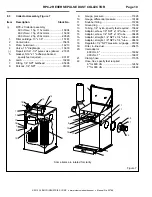
4.3.7
Fine-tuning is required for optimum reclaimer
efficiency. After adjusting the damper to the best
balance of media recovery and media cleaning, carry-
over, or dirty media continues to be a problem, the
adjustable vortex cylinder may need adjustment. Consult
the cabinet manual or reclaimer manual for vortex
adjustment.
4.4 Manometer
NOTE:
These instructions show several methods of
taking static pressure readings (negative pressure) on
cabinet reclaimers, using a flexible tube manometer.
Use the method best suited for the application. The
instructions explain the processes for taking periodic
readings and how to permanently install the manometer
for taking frequent readings. Permanent fittings should
be installed when rigid ducting is used, or when the
manometer installation is permanent. Use silicone sealer
or other sealant to seal around the fitting to prevent
leaks. The fitting should be capable of being capped
when the manometer tube is removed. This will prevent
leaks that alter the reclaimer’s separation efficiency.
Taking readings at different locations could produce
different readings. Static pressure readings at the door
are generally .5" to 1" lower than those taken above the
reclaimer. The readings are reference points, so
readings should be taken using the same method each
time the reading is taken.
4.4.1
Refer to directions packed with the manometer
for preparation and operating instructions for the
manometer.
4.4.2
Connect one end of the 3/16" ID tubing to one of
the tubing connectors (elbow) at the top of the
manometer, by pushing it over the barbed adaptor.
4.4.4
Leaving the needle protector on the needle,
insert the needle into the other end of the tubing. The
ends of the tubing must fit tight on the manometer and
needle; leaks will give inaccurate readings.
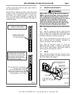
WARNING
Do not remove the needle shield during the
assembly. The needle is difficult to fit into the
tubing, and the shield protects the installer
from needle punctures.
4.4.5
Open both manometer valves (elbows fittings).
Both valves must be open to obtain a reading. Refer to
the supplement manual supplied with the manometer for
operation.
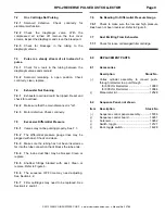
Figure
4
4.4.6
Place the manometer on the side of the
reclaimer; magnets on the manometer hold it in position.
The manometer must be vertically-plumb so the fluid is
level on both sides of the tube.
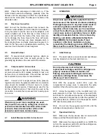
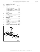
4.4.7
Needle placement: Ref. Figure 4.
4.4.7.1
Remove the needle protector, and place the
needle using one of the methods shown in Figure 4.
4.4.8
Turn ON the exhauster. The negative (static)
pressure will move fluid in the tube.
NOTE: Readings must be taken with the cabinet
doors open, and with the exhauster running.
4.4.9
To find the static pressure, add the number of
inches the fluid travels up column one column to the
8
Insert the needle into
straight section of flex
hose, about 8-inches above
the top of the reclaimer.
Place the needle so the
point is inside the door
opening. Carefully close
the door on the needle.
For taking frequent readings,
install a permanent fitting in
the reclaimer wall, just below
the inner cone as shown.
Reclaimers are for reference and
may differ from those shown.