


RPC-2 REVERSE PULSE DUST COLLECTOR
Page 5
© 2012 CLEMCO INDUSTRIES CORP.
www.clemcoindustries.com
Manual No. 22788
3.2.3
Start the exhauster at the control panel, usually
mounted on the blast cabinet.
3.2.4
Check the pulse manifold pressure.
3.3 Shutdown
3.3.1
Run the collector until all media is recovered from
the cabinet, and the cabinet is free of airborne dust.
3.3.2
Turn off the exhauster.
3.3.3
Turn off the compressed air supply valve.
3.3.4
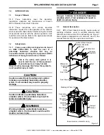
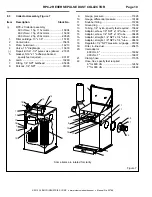
Drain the pulse manifold whenever the
compressed air supply is turned off. The drain petcock is
mounted on the side of the collector. See Figure 1.
3.3.5
Empty contents of the dust drawer into a
suitable container, per Section 5.1.
4.0 Adjustments
4.1
Pulse Manifold Pressure
4.1.1
The pressure regulator located on the pulse
manifold inlet, adjust pulse pressure. Set initial pressure
at 70 psi. Refer to Section 4.2.4.
4.1.2
Do not increase pulse pressure until the pulse
sequence is at maximum intervals as describe in Section
4.2.
4.2
Pulse Sequence Control Panel and Timer
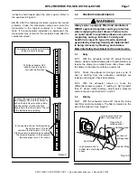
4.2.1
The toggle switch (sequence switch) mounted on
the sequence control panel cover, enables or disables the
timing sequence. When the switch is ON, the pulse
sequence automatically starts when the dust collector
exhauster is started. If the switch is OFF the pulse
sequence will not occur. The switch should be left OFF
(no pulse) until cartridges are seasoned. See Section 6.2.
4.2.2
The timer is factory set at 40 seconds OFF and
15/100 of a second ON. Every 40 seconds the cartridges
are pulsed.
4.2.3
As the cartridges cake with dust, the pulse may
not clean them well enough to bring the differential
pressure gauge below the recommended changeover
pressure of 4". A constant reading higher than 4" is an
indication that more frequent pulse cycles or higher
pressure are needed. When the differential pressure
gauge shows a constant pressure difference greater than
4", adjust the OFF time setting by half. DO NOT ADJUST
ON TIME. Increasing on time will consume more air, but
will NOT increase cleaning efficiency.
4.2.4
When the frequency of the pulse cycles will not
lower the differential pressure to less than 4", or if a
decrease in the efficiency is noted, increase pulse
pressure in increments of 10 psi until the maximum of 100
psi is reached.
4.2.5
When the frequency of the pulse cycles and
higher pulse pressure will not lower the differential
pressure below the changeover pressure of 4" w. c., the
filter cartridges should be replaced, and the timer OFF
time should be reset to 40 seconds, and pressure set to 70
psi. See Section 6.1.
4.3 Damper
Setting
(Static Pressure)
4.3.1
Static pressure must be adjusted for optimum
reclaimer efficiency. Correct static pressure varies with
size of reclaimer and the size, weight and type of media.
4.3,2
Adjust static pressure using the damper located
on the dust collector exhauster outlet at the base of the
silencer, and the manometer provided with the dust
collector.
4.3.3
Adjust static pressure by further opening the
damper (handle toward vertical) to increase static
pressure or further closing the damper (handle toward
horizontal) to decrease static pressure. Open only as far
as necessary to obtain a balance of dust removal without
media carryover.
4.3.4
If the static pressure is too low, the results will
be dirty media. Dirty media consists of good media, dust,
fines, and blasting by-products.
4.3.5
If the static pressure is too high, it may cause
carryover (usable media carried into the dust collector)
and result in excessive media consumption.
4.3.6
Use the manometer, and adjust the damper to
obtain the pressure in inches of water, as specified below.
The measurements are starting points only. With light-
weight, or finer media the setting may need to be lower;
with heavier and coarse media the setting may need to be
higher.
Media
Size
Static
Pressure
Glass Bead 5 to 7 ........................ 3-1/2 to 4 inches
Glass Bead 8 to 13 ..................... 3 to 3-1/2 inches
Al. Oxide
60 and coarser .............. 4 to 5 inches
Al. Oxide
80 and finer ................... 3 to 4 inches
Plastic
All
*
.........................
2-1/2 to 3 inches
Steel Grit
** ................................... 6 to 7 inches
*
Non-Aerolyte reclaimers require modification.
Consult the factory.
**
Size is limited, and determined by the system’s
application.


