background image


The device should be checked immediately after delivery for damages which might have 
occurred during transportation.  Please contact your supplier immediately if damages can be 
identified. 


The device should be cleaned properly before setting it into operation.  For this, lukewarm water 
and a mild cleaning agent must be used only.  Abrasive or caustic cleaning agents, steel wood, 
scouring sponges, or chemical cleaning agents should in no case be used.  After the cleaning is 
finished, the device should be dried properly. 


Ensure that the device is placed at a cool location, away from heat sources, and not being 
exposed to direct sunlight.  The room must be ventilated properly.  The device must not be 
exposed to air draught conditions.  The unit covering, i.e. the venting slots and the chimney 
opening must not be blocked. 


To ensure proper function, the device must be standing horizontally.  Use a water level to check 
and to correct if necessary. 


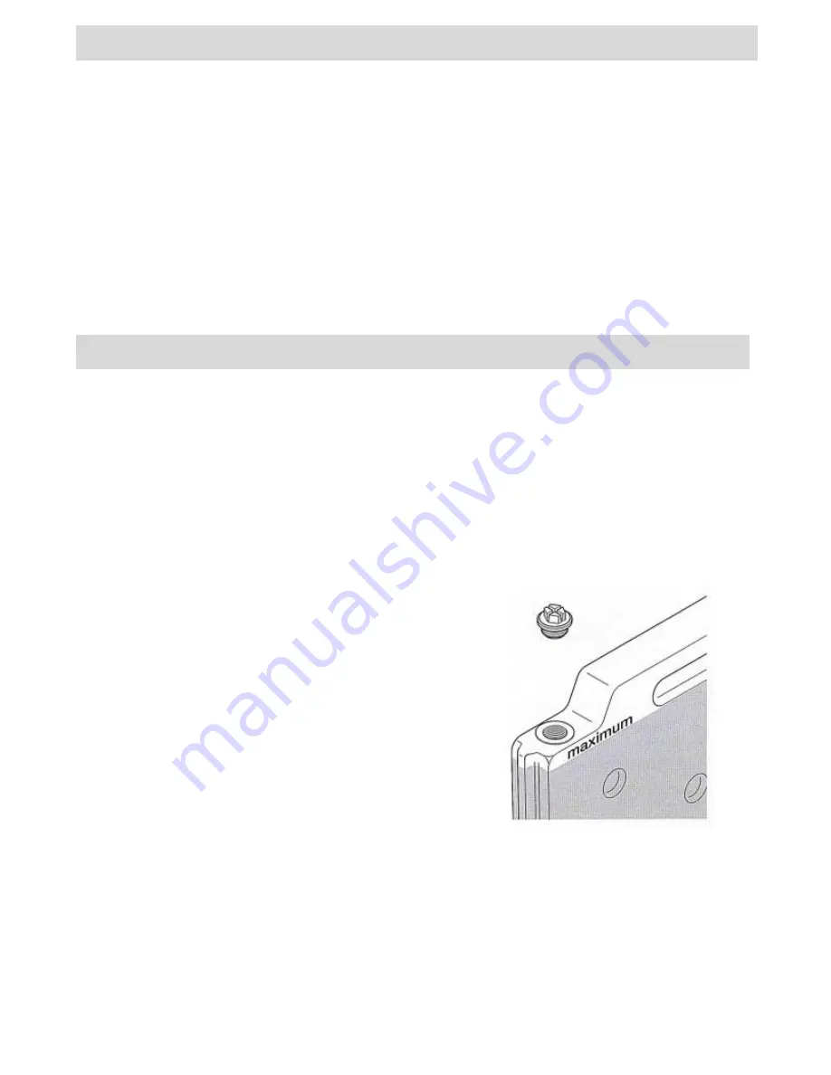
2 aluminum and 2 water isolating inserts are included with the delivery.  The use of these isolating inserts 
is subject to the ambient temperature. 


Use the water isolation inserts at ambient temperatures up to +32°C. 


Use the aluminum & plastic isolation inserts at ambient temperatures higher than +32°C (up to 
+43°C at maximum). 

 
The isolation inserts must be pushed into the slot on the left and right side of the freezer section. 
 

2 isolation inserts must always be installed.  If only one isolation insert is installed, the temperature in the 
cooling section without an isolation insert will become too 
cold. 


The plastic isolation inserts must be filled up to the indicated 
maximum level with cold, clean water before starting 
operation.  Do not fill the isolation inserts completely!  The 
upper section must be kept Free. 


Page 3 

I

NSTALLATION 

I

NSTRUCTIONS 

I

NSTALLATION OF THE 

I

SOLATION 

I

NSERTS 

Summary of Contents for VSRF60GE

Page 1: ...Installation Service and User INSTRUCTIONS FOR THE ZERO MODEL VSRF60GE SINGLE LID VACCINE REFRIGERATOR ICEPACK FREEZER 2 WAY L P Gas 230V Electric ZERO APPLIANCES PTY LTD Cat I3 28 30 37 I3B P 30...

Page 2: ...EPLACING THE THERMOCOUPLING CLEANING REPLACING THE BURNER JET REPLACING THE COOLING UNIT WIRING DIAGRAM IMPORTANT NOTES THIS DEVICE CAN ALTERNATIVELY BE OPERATED WITH GAS OR ELECTRICAL ENERGY THE DEVI...

Page 3: ...cked To ensure proper function the device must be standing horizontally Use a water level to check and to correct if necessary 2 aluminum and 2 water isolating inserts are included with the delivery T...

Page 4: ...eased setting increased cooling capacity Turn the thermostat switch counter clockwise to position 0 and unplug the mains cable to switch off the device when it is operated with alternating current Whe...

Page 5: ...ply valve at the gas cylinder Press the safety pilot switch for about 10 seconds Gas will flow through the line and will vent the gas line to the burner The ignition of the burner can be viewed throug...

Page 6: ...to the evaporator as hard as possible The refrigerator should be cleaned inside and outside before it is set into operation and afterwards in regular intervals Use lukewarm water with a mild cleaning...

Page 7: ...1 cm the device must be defrosted See section Defrosting Clean the lid sealing and verify that the lid is locking tightly MONTHLY Use a soft brush to free the unit from dust Clean the device inside a...

Page 8: ...lation inserts frozen Defrost isolation insert and select warmer thermostat setting if necessary Heating cartridge defective Replace heating cartridge False operating voltage Check power supply Poor c...

Page 9: ...ection of the arrow until it opens Remove the cooker insulation Undo the heater s connection flex from the terminal block and remove the cable clip from the back wall of the appliance Unscrew the heat...

Page 10: ...copper tube carefully out of the safety pilot see the section REPLACING THE GAS THERMOSTAT Dismantle the base of the burner A undo the screw and pull down the base of the burner Remove the safety plat...

Page 11: ...be used for cleaning To install proceed in reverse order Ensure the burner tube C is positioned correctly slot facing upwards Then check all screw connections for imperviousness Page 14 Dismantle the...

Page 12: ...ews disconnect the earth wire from the unit and pull the unit backwards out of the container To install the new unit proceed in reverse order Remove the refrigerator lead paste from the old unit s eva...

Reviews: