9
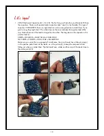
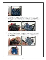
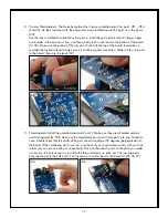
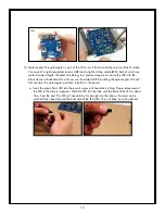
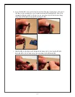
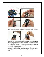
5. Flip the board over solder-side-up, and solder all of the components in one pass.
6. Clip the leads off with small diagonal cutters, right at the solder joint.
When soldering the components in this kit, try to keep them from getting too hot. Most components
have a temperature threshold that shouldn’t be exceeded. As a rule of thumb don’t keep your iron on
any leg longer than two seconds, and make sure the component stays cool enough to touch. If you find
you have a hard time keeping any component from getting too hot, just solder one leg at time and let
the part cool off before proceeding to the next leg. It’s a good idea to take your time with the assembly
process to ensure nothing goes wrong.
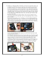
You will notice that we have already installed several components on the solder-side of the PCB.
These components are surface mounted, which are a little more difficult to solder than standard hole-
through components (like what you will be soldering on the board). Some of the surface mounted
components are sensitive to static electricity, meaning they can easily get damaged if they are exposed
to moderately high voltages. Unfortunately (or fortunately), humans are not sensitive to static electricity
at these levels; in fact, most people can’t even feel a static discharge less than around 1000 volts!
So it is easy to damage these components without even knowing it. Since these components are
already soldered to the circuit board, they are less likely to be damaged by static discharge but it is
still important to be mindful of these principles in handling them. When you handle the circuit board
(before you take it out of its anti-static bag, and throughout the assembly process), make sure you are
grounded, preferably by touching something grounded to the electrical mains like the metal chassis of
a plugged-in amplifier, or a refrigerator. At the very least you should touch a large conductive object
like a metal desk or a filing cabinet. With this information in mind, please proceed carefully.
HEAD- PHONES
SPEAKER
ZEPPELIN
DESIGN LABS
NOISETTE
OPTICAL THEREMIN V1.2
Figure 3: Component Values and Locations


