PV154 - 923-03499
10
P50W26 - SERVICING
SERVICING
Va voltage
adjustment
variable resistor
VR4
VR1
DMM
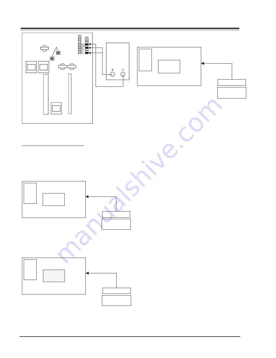
<Fig 1> Connection Diagram of Power Adjustment
ADJUSTMENT OF WHITE BALANCE
REQUIRED EQUIPMENT
Color analyzer (CA-100 or same product)
CONNECTION DIAGRAMS (MANUAL ADJUSTMENT)
High Light
216 Gray Level
135 140Cd/
RGB Signal Input
PDP MONITOR
§‡
R-L 70
G-L 70
R-M 128
G-M 128
R-H 216
G-H 216
COLOR
ANALYZER
CA-100
MSPG-2100 or
MSTG-5200
Window
<Fig 2> Connection Diagram of Manual
Adjustment(High Light)
Middle Light
128 Gray Level
70~75Cd/
RGB Signal Input
PDP MONITOR
§‡
R-L 70
G-L 70
R-M 128
G-M 128
R-H 216
G-H 216
COLOR
ANALYZER
CA-100
MSPG-2100 or
MSTG-5200
Window
Fig 3> Connection Diagram of Manual
Adjustment(Middle Light)
Low Light
70 Gray Level
20~25Cd/§‡
RGB Signal Input
PDP MONITOR
R-L 70
G-L 70
R-M 128
G-M 128
R-H 216
G-H 216
COLOR
ANALYZER
CA-100
MSPG-2100 or
MSTG-5200
Window
<Fig 4> Connection Diagram of Manual
Adjustment(Low Light)
ADJUSTMENT OF WHITE BALANCE
Operate the Zero-calibration of the CA-100, then stick
sensor to PDP module surface when you adjust. For
manual adjustment, it is also possible by the following
sequence.
1) Select WHITE PATTERN of HEAT RUN mode by press-
ing POWER ON KEY on remote control for adjust-
ment then operate HEAT RUN more than 15 minute.
2) Supply 216Gray, 128Gray, 70Gray Level, 50% size
length and breadth signal to RGB1 input. (Refer
to Fig 2,3,4)
3) W/B adjustment must be adjusted once and follow
the sequence of Low Light —> Middle Light —>
High Light and then save the adjustment value
with o Key.
4) To adjust Low Light, stick sensor to Gray Level(or
20~25 Cd/m2) Pattern, press ADJ Key on R/C for
adjustment and press v, x on R/C in adjustment
mode to select R-L or G-L, press VOL +, - Key and
adjust it until color coordination becomes as be-
low.
X: 0.290±0.003, Y: 0.300±0.003
Color temperature: 8, 500
o
K±500
o
K
5) To adjust Middle Light , stick sensor to Gray Level
(or 70~75 Cd/m2) Pattern, press ADJ Key on R/
C for adjustment and press v, x on R/C in adjust-
ment mode to select R-M or G-M, press VOL +, -
Key and adjust it until color coordination becomes
as below.
X: 0.290±0.003, Y: 0.300±0.003
Color temperature: 8, 500
o
K±500
o
K
6) To adjust High Light, stick sensor to Gray Level(or
135-140 Cd/m2) Pattern, press ADJ Key on the
R/C for adjustment and press v, x on R/C in ad-
justment mode to select R-L or G-L, press VOL +,
- Key and adjust it until color coordination be-
comes as below.
Summary of Contents for P50W26
Page 4: ......
Page 8: ......
Page 21: ......
Page 22: ......
Page 25: ...29 P50W26 DIAGRAMS PV154 923 03499 P50W26 Block Diagram...
Page 26: ...30 P50W26 DIAGRAMS PV154 923 03499 P50W26 Main PCB M A I N TOP...
Page 28: ...32 P50W26 DIAGRAMS PV154 923 03499 P50W26 Other PCBs...


