


7
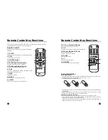
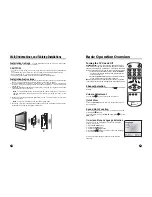
Controls
6
Supplied Accessories
2
8
1
7
3
4
5
6
POWER TV/AV
MENU
- CH +
- VOL +
9
10
11
12
13
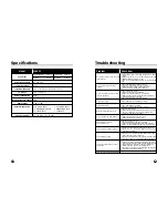
<Front Panel>
<Rear Panel>
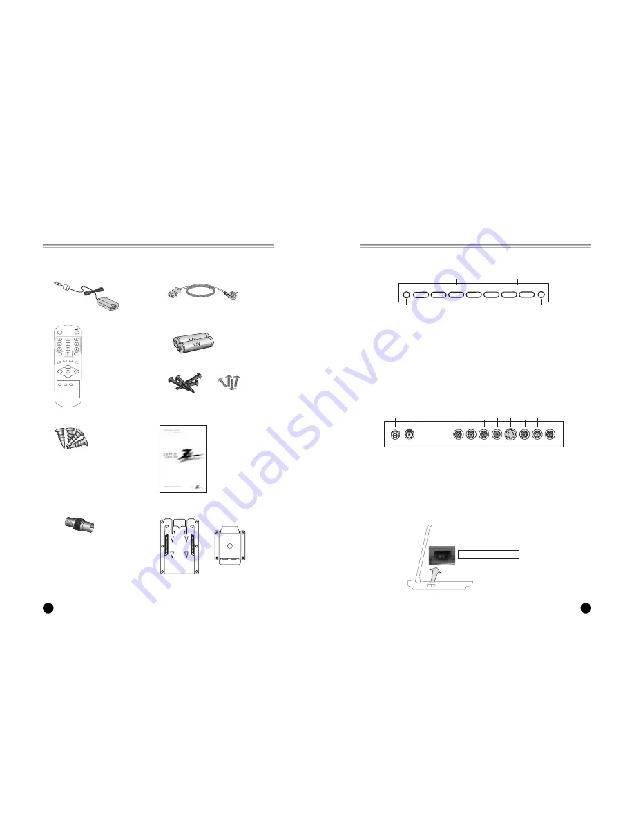
<Side Panel>
1. POWER/STANDBY INDICATOR
Illuminates brightly when the set is in
standby mode.
Dims when the set is switched on.
2. POWER
Turns the TV on and off.
3. TV/AV
Selects TV, COMPONENT, VIDEO or S-
VIDEO modes.
Clears the menu from the screen.
4. MENU
Displays a menu.
5. + CH - (Channel Up/Down)
Selects next channel or a menu option.
6. +VOL -(Volume Up/Down)
Adjusts the sound level.
Adjusts menu option settings
7. REMOTE CONTROL SENSOR
8. Ant. (Antenna Input)
9. DC 12V Adapter input
10. COMPONENT INPUT
11. HEADPHONE Input
Connect a headphone to this input.
12. S-VIDEO Input
Connect the output of an S -VIDEO VCR
to the S-VIDEO input.
Connect the audio outputs of an S-VIDEO
VCR to the AV-IN audio inputs.
13. A/V IN Inputs
Connect the Audio/Video outputs of
external equipment to these inputs.
Main Power switch
ANT. DC-12V
COMPONENT INPUT H/P S-VIDEO
AV-IN
• Make sure all the accessories are included with TV.
1. DC Adapter
2. AC Cord
4. Batteries (size AAA)
5. Metal Screws (2 Types)
9. Brackets
3. Remote Control
POWER
SSM
C
VOL
VOL
B
MENU
CC
MEMORY SLEEP
TV/AV
ST/SAP Q.VIEW
PSM
OK
PR
W
PR
V
6. Plastic Drywall Anchors
7. Owner’s Manual
8. Antenna Adapter


