background image

(Continued from previous page)

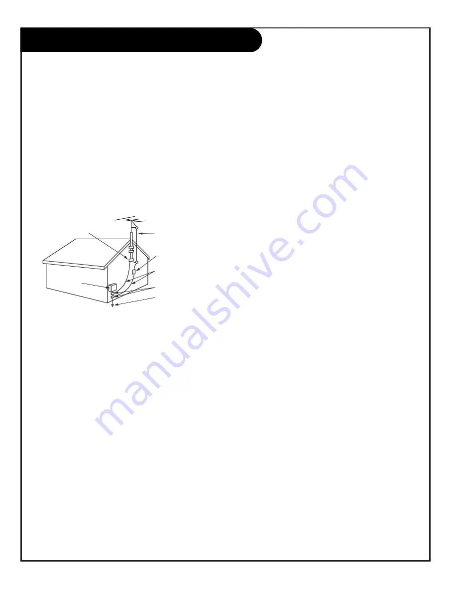
14. Outdoor Antenna Grounding

If an outside antenna or cable system is connected to the
product, be sure the antenna or cable system is grounded
so as to provide some protection against voltage surges
and built-up static charges. Article 810 of the National
Electrical Code (U.S.A.), ANSI/ NFPA 70 provides 
information with regard to proper grounding of the mast
and supporting structure, grounding of the lead-in wire to
an antenna discharge unit, size of grounding conductors,
location of antenna-discharge unit, connection to 
grounding electrodes, and requirements for the grounding
electrode.

15. Lightning

For added protection for this product (receiver) during a
lightning storm, or when it is left unattended and unused
for long periods of time, unplug it from the wall outlet and
disconnect the antenna or cable system. This will prevent
damage to the product due to lightning and power-line
surges.

16. Power Lines

An outside antenna system should not be located in the
vicinity of overhead power lines or other electric light or
power circuits, or where it can fall into such power lines or
circuits. When installing an outside antenna system,
extreme care should be taken to keep from touching such
power lines or circuits as contact with them might be
fatal.

17. Overloading

Do not overload wall outlets and extension cords as this
can result in a risk of fire or electric shock.

18. Object and Liquid Entry

Never push objects of any kind into this product through
openings as they may touch dangerous voltage points or 

short-out parts that could result in a fire or electric shock.
Never spill liquid of any kind on the product.

19. Servicing

Do not attempt to service this product yourself as opening
or removing covers may expose you to dangerous voltage
or other hazards. Refer all servicing to qualified service
personnel.

20. Damage Requiring Service

Unplug this product from the wall outlet and refer servic-
ing to qualified service personnel under the following 
conditions:

a. If the power-supply cord or plug is damaged.

b. If liquid has been spilled, or objects have fallen into

the product.

c. If the product has been exposed to rain or water.

d. If the product does not operate normally by following

the operating instructions. Adjust only those controls that
are covered by the operating instructions as an improper
adjustment of other controls may result in damage and will
often require extensive work by a qualified technician to
restore the product to its normal operation.

e. If the product has been dropped or the cabinet has

been damaged.

f. If the product exhibits a distinct change in 

performance.

21. Replacement Parts

When replacement parts are required, be sure the service
technician has used replacement parts specified by the
manufacturer or have the same characteristics as the 
original part. Unauthorized substitutions may result in fire,
electric shock, or other hazards.

22. Safety Check

Upon completion of any service or repairs to this product,
ask the service technician to perform safety checks to
determine that the product is in proper operating 
condition.

23. Wall or Ceiling Mounting

The product should be mounted to a wall or ceiling only as
recommended by the manufacturer. The product may slide
or fall, causing serious injury to a child or adult, and seri-
ous damage to the product.

24. Heat

The product should be situated away from heat sources
such as radiators, heat registers, stoves, or other products
(including amplifiers) that produce heat.

P A G E   4

IMPORTANT SAFETY INSTRUCTIONS

3706 2-WR-POLZ

Antenna Lead in Wire

Antenna Discharge Unit
(NEC Section 810-20)

Grounding Conductor
(NEC Section 810-21)

Ground Clamps

Power Service Grounding
Electrode System (NEC
Art 250, Part H)

Ground Clamp

Electric Service

Equipment

NEC - National Electrical Code

Example of Grounding According to National Electrical
Code Instructions

Summary of Contents for H27F56DT

Page 1: ...Copyright 2003 Zenith Electronics Corporation Installation and Operating Guide Warranty Model Numbers H27F56DT H27F56S H32F56S H32F56DT Direct View TVs t a b l e o f c o n t e n t s p a g e 5...

Page 2: ...e reasonable protection against harmful interference when the equipment is operated in a residential installation This equipment generates uses and can radiate radio frequency energy and if not instal...

Page 3: ...ions and should use a mounting accessory recommended by the manufacturer 8 Transporting Product A product and cart combination should be moved with care Quick stops excessive force and uneven surfaces...

Page 4: ...service personnel 20 Damage Requiring Service Unplug this product from the wall outlet and refer servic ing to qualified service personnel under the following conditions a If the power supply cord or...

Page 5: ...lection 20 Source Menu 21 On Screen Menus Overview 22 Other Menus and On Screen Displays Channel Time Audio Display 23 Sleep Timer menu 23 Volume Display 23 Closed Captions Text menu 23 Ch Preview men...

Page 6: ...new channel Use to key in numbers on menus SLEEP TIMER Press repeatedly to choose a TV turn off time up to 4 hours Use to set AM PM on the Alarm menu VOLUME DOWN UP Adjusts the sound level CHANNEL PR...

Page 7: ...access to closed captions Press ENTER to exit A list of the keys on the optional LP702 installer s remote and what they do ALARM Press to go to the Alarm menu Set a time for the TV to turn itself on...

Page 8: ...R L AUDIO Connection for standard component video equipment or DVD player DVD Player 480i SDTV Set top Box 480i VIDEO IN R L AUDIO IN Use these input jacks to con nect external audio video equipment...

Page 9: ...Video VCR DVD Player etc page 14 IMPORTANT Use this page to decide where you need to begin your set up First find the line below that best describes what you want to do then go to that page number Cab...

Page 10: ...included with the Zenith TV 300 TO 75 OHM ADAPTER Typical TV Back S Video In M P I R Audio In L S Video Out Antenna Cable Component Video Input R Audio In L R Audio L Video In Y Pr Pb Matrix Out Flat...

Page 11: ...Coaxial Wire 75ohm Typical TV Back S Video In M P I R Audio In L S Video Out Antenna Cable Component Video Input R Audio In L R Audio L Video In Y Pr Pb Matrix Out Cable TV Wall Jack Cable Box In Out...

Page 12: ...uded with TV Typical TV Back S Video In M P I R Audio In L S Video Out Antenna Cable Component Video Input R Audio In L R Audio L Video In Y Pr Pb Matrix Out In Out Audio Video 3 4 VCR Back VCR Back A...

Page 13: ...ack RF Coaxial Wire 75ohm Typical TV Back S Video In M P I R Audio In L S Video Out Antenna Cable Component Video Input R Audio In L R Audio L Video In Y Pr Pb Matrix Out In Out Audio Video 3 4 VCR Ba...

Page 14: ...go to the Source menu on page 21 Hook up your S Video type VCR or DVD player to the TV according to the diagram Remove the back of the remote and put in two AA batteries Plug in your TV The TV is des...

Page 15: ...nected to a Component Video device like a DVD player or other component video source To use this equipment you must use the optional LP702 remote control refer to the Source menu on page 21 Hook up yo...

Page 16: ...l Audio Output Use the Matrix Out jack to connect an external monaural speaker or amplifier to the TV 1 External Monaural Speaker Hookup Typical TV Back S Video In M P I R Audio In L S Video Out Anten...

Page 17: ...S Video input jacks as shown 3 On the Daisy chained TVs select the S Video Input for the picture source Viewing Sources Note Follow instructions supplied with your TV s for selecting viewing sources...

Page 18: ...the channel search is complete 1 2 3 4 5 6 7 AUTO PROGRAM ADD DEL BLNK CH LABELS CLOCK SET TIMER CAPTIONS LANGUAGE TO PROGRAM SETUP MENU Mini glossary OFF AIR ANTENNA If only over the air channels ar...

Page 19: ...The front Video jacks are Auto Sense source connec tions With cables connected the TV will automati cally change its source setting to CAMPORT or FRNT Y C Front S Video as indicated on the channel ti...

Page 20: ...9 on the remote number keypad Note The Installer by changing options in the service menu can change the default setup and determine what source connections are available Auto Source Sense connections...

Page 21: ...ted source and to remove the menu Notes Selectable sources appearing in the Source menu may vary depending on the installation setup for Auto Sense sources in the Installer menu Auto Sense sources app...

Page 22: ...re Contrast Brightness Color Tint Sharpness Picture Pref PARENTAL 33 Allows user to block program content or the A V sources for up to 99 hours with the use of a password CONTROL MENU Other Menus and...

Page 23: ...u Press CH PREVIEW Displays list of the available TV Channels Aux source and provides access to the Parental Control menu Closed Captions Menu Press CC Turns selected option on or off See Caption Text...

Page 24: ...e Installer s remote so the Setup menu appears Press SELECT repeatedly to highlight the Add Del Blnk option Using either the NUMBER keypad and ENTER or the Channel Up Down arrow on the remote select a...

Page 25: ...e finished press ENTER to remove menu 1 2 3 4 AUTO PROGRAM ADD DEL BLNK CH LABELS CLOCK SET TIMER CAPTIONS LANGUAGE CH 32 ABC SETUP MENU Mini glossary The 4 dashes will allow a channel label to appear...

Page 26: ...to scroll the available preset labels Scroll past scroll past NONE to go to the first programmable label slot LAB 1 Notice that the label appears with the title LAB 1 Creating a Custom Channel Label...

Page 27: ...te use MENU SELECT and the ADJ Left Right arrows to choose and set up the Clock menu options Use the number keypad or the Left Right ADJ arrows to set the time Use TIMER to set AM PM Clock Set Auto TV...

Page 28: ...will turn itself Off each day On Off Timer Enables or disables the On Off Timer functions The On Off Timer can be disabled but the settings will be retained 1 2 3 4 1 AUTO PROGRAM ADD DEL BLNK CH LAB...

Page 29: ...NU TO SET CAPTIONS AUTO PROGRAM ADD DEL BLNK CH LABELS CLOCK SET TIMER CAPTIONS LANGUAGE SETUP MENU Mini glossary CAPTIONS The term for the words that scroll across the bottom of your TV screen usuall...

Page 30: ...staller s remote press MENU repeatedly until the Setup menu appears Use SELECT on the remote control to highlight the Language option on your screen Use the Left Right ADJ arrow to choose one of the f...

Page 31: ...ontrol highlight the audio option you want to change Choose from Bass Increases decreases lower end sounds Treble Increases decreases higher end sounds Balance Allows you to put the sound more to the...

Page 32: ...icture Preference Choose either Custom or Preset Custom allows you to set the picture the way you want Preset moves all the above options back to their original factory set levels Using SELECT on the...

Page 33: ...ogram Content based on individual parameters such as Strong Dialog Bad Language Sex Scenes Violence Scenes or Fantasy Violence Scenes in the Content Blk option How many hours do you want Parental Cont...

Page 34: ...an option like Content Block then press the Right ADJ arrow Use SELECT and the Left Right ADJ arrows to select and adjust or set the rating for an option For Sex Scenes for example use the From TV PG...

Page 35: ...Default Block Hours You can change the Block hours from the 12 hour default setting to up to 99 hours In the Installer s Menu item 22 I MAX BLK HRS 12 use the ADJ Left Right adjust arrow to set a dif...

Page 36: ...menu 25 I FUNCTION PRE 0 3 0 Controls channel preview in Pay Per View function menu Use the Installer Menu to set up or change operational settings See descriptions of the Installer items on the foll...

Page 37: ...switch to Component input 45 I AUTO REAR VIDEO 0 1 0 Set to 1 to automatically switch to rear AUX video input 46 I STRT AUX SRCE 0 2 255 255 Set the starting AUX source 47 I AUX STATUS 0 1 0 Set to 1...

Page 38: ...ek 80 I UPN MSB 2 0 255 255 User programmable number most significant byte 2 SN HIGH 81 I UPN LSB 0 255 255 User programmable number least significant byte SN LOW 82 I CHKSM ERROR 0 1 0 Enforces rigid...

Page 39: ...lt is 0 or OFF NOTE When captions are on Ghost Channel is not displayed 7 I START VOLUME This function allows the Installer to determine the initial volume level setting when the TV is turned ON This...

Page 40: ...ate after TV turns off When set to 0 Captions are always off when TV is initially turned on 24 I TEXT MODE Determines whether TEXT 1 TEXT 2 TEXT 3 or TEXT 4 decoding is enabled when TEXT is turned on...

Page 41: ...ically switch viewing source to rear AUX Video input when equipment is connected Set to 0 to disable rear AUX Video automatic source selection 46 I STRT AUX SRCE Sets the starting AUX source 47 I AUX...

Page 42: ...OR SRC M Source Menu Foreground Color 0 Black 3 Yellow 6 Cyan 1 Red 4 Blue 7 White 2 Green 5 Violet 68 I BCK SRC M Source Menu Background Color 0 Black 3 Yellow 6 Cyan 1 Red 4 Blue 7 White 2 Green 5 V...

Page 43: ...ke time which is 64 msec thus relaxing M P I timing requirements to be compatible with PC based Windows controlled systems range is 0 5 Set to 0 to retain standard 64 msec delay Set to 1 5 to increase...

Page 44: ...THE TV THE CLONE IS VERSION XX THE TV IS VERSION XX THE SW IS REVISION XX CLONE CLOCK XX XX TV CLOCK XX XX PRESS ANY KEY TO CONTINUE DISCONNECT CLONE WHEN DONE Clone Controlling TV Display Before you...

Page 45: ...you can set the Master TV s clock by copying the time from the Clone pro grammer The Clone Programmer can copy the current time to both a master TV and to the Clone s internal clock accurate to withi...

Page 46: ...k setup instructions accompanying the LT2000 clone programmer Use the printed menu illustrations on the quick setup sheet supplied with the Clone as an aid to making your programming choices Although...

Page 47: ...aption Text mode turned on The CC closed caption option may be in Text 1 2 3 or 4 mode on it but the sound is O K Select Caption 1 or OFF in the Caption Text menu No Closed Captions or Text Not availa...

Page 48: ...or Audio muted Press MUTE or volume right key to increase sound level 6 7 or no sound Broadcast problem Try a different channel 6 7 19 A V cables incorrectly connected Install A V cables correctly 12...

Page 49: ...t audio for S Video to Audio In R L 14 19 20 Use Audio In L jack to connect one audio wire Antenna Cable Front Video connected Disconnect equipment connected to front Video 19 20 not selectable S Vide...

Page 50: ...again 3 Let the cabinet air dry before turning the TV on Use a quality wood cleaner and polish This will protect the TV from dirt and dust as well as keep the cabinet looking new If the TV will be do...

Page 51: ...vailable BLANK Channels that are Blanked will not have Video shows a blank screen only audio if present on channel DELETED Lets you remove channels from the list that the user will scroll through usin...

Page 52: ...Y EXPRESS OR IMPLIED INCLUDING WITHOUT LIMITATION ANY WARRANTY OF MERCHANTABILITY OR FITNESS FOR A PARTICULAR PURPOSE AND ZENITH SHALL NOT BE LIABLE FOR ANY CONSEQUENTIAL INDIRECT OR INCIDENTAL DAMAGE...

Reviews: