background image

(Continued from previous page)

14. Outdoor Antenna Grounding

If an outside antenna or cable system is connected to the
product, be sure the antenna or cable system is grounded
so as to provide some protection against voltage surges
and built-up static charges. Article 810 of the National
Electrical Code (U.S.A.), ANSI/ NFPA 70 provides informa-
tion with regard to proper grounding of the mast and sup-
porting structure, grounding of the lead-in wire to an
antenna discharge unit, size of grounding conductors, loca-
tion of antenna-discharge unit, connection to grounding
electrodes, and requirements for the grounding electrode.

15. Lightning

For added protection for this product (receiver) during a
lightning storm, or when it is left unattended and unused
for long periods of time, unplug it from the wall outlet and
disconnect the antenna or cable system. This will prevent
damage to the product due to lightning and power-line
surges.

16. Power Lines

An outside antenna system should not be located in the
vicinity of overhead power lines or other electric light or
power circuits, or where it can fall into such power lines or
circuits. When installing an outside antenna system,
extreme care should be taken to keep from touching such
power lines or circuits as contact with them might be
fatal.

17. Overloading

Do not overload wall outlets and extension cords as this
can result in a risk of fire or electric shock.

18. Object and Liquid Entry

Never push objects of any kind into this product through
openings as they may touch dangerous voltage points or
short-out parts that could result in a fire or electric shock.
Never spill liquid of any kind on the product.

19. Servicing

Do not attempt to service this product yourself as opening
or removing covers may expose you to dangerous voltage
or other hazards. Refer all servicing to qualified service
personnel.

20. Damage Requiring Service

Unplug this product from the wall outlet and refer servic-
ing to qualified service personnel under the following con-
ditions:

a. If the power-supply cord or plug is damaged.

b. If liquid has been spilled, or objects have fallen into

the product.

c. If the product has been exposed to rain or water.

d. If the product does not operate normally by following

the operating instructions. Adjust only those controls that
are covered by the operating instructions as an improper
adjustment of other controls may result in damage and will
often require extensive work by a qualified technician to
restore the product to its normal operation.

e. If the product has been dropped or the cabinet has

been damaged.

f. If the product exhibits a distinct change in perform-

ance.

21. Replacement Parts

When replacement parts are required, be sure the service
technician has used replacement parts specified by the
manufacturer or have the same characteristics as the origi-
nal part. Unauthorized substitutions may result in fire,
electric shock, or other hazards.

22. Safety Check

Upon completion of any service or repairs to this product,
ask the service technician to perform safety checks to
determine that the product is in proper operating condi-
tion.

23. Wall or Ceiling Mounting

The product should be mounted to a wall or ceiling only as
recommended by the manufacturer.

24. Heat

The product should be situated away from heat sources
such as radiators, heat registers, stoves, or other products
(including amplifiers) that produce heat.

P A G E   4

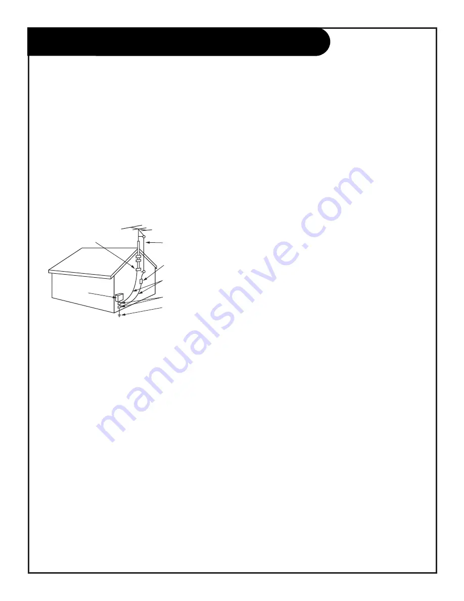
Antenna Lead in Wire

Antenna Discharge Unit
(NEC Section 810-20)

Grounding Conductor
(NEC Section 810-21)

Ground Clamps

Power Service Grounding
Electrode System (NEC
Art 250, Part H)

Ground Clamp

Electric Service

Equipment

Example of Grounding According to National Electrical
Code Instructions

NEC - National Electrical Code

IMPORTANT SAFETY INSTRUCTIONS

206-3588

Summary of Contents for C25A24T

Page 1: ...e n j o y t h e v i e w o p e r a t i n g g u i d e w a r r a n t y h o o k u p d i r e c t o r y p a g e 5 Copyright 2000 Zenith Electronics Corporation machine numbers C25A24T C27A24T...

Page 2: ...e provides guidelines for proper grounding and in particular specifies that the cable ground shall be connected to the grounding system of the building as close to the point of the cable entry as prac...

Page 3: ...w the manufacturer s instructions and should use a mounting accessory recommended by the manufacturer 8 Transporting Product A product and cart combination should be moved with care Quick stops excess...

Page 4: ...oltage or other hazards Refer all servicing to qualified service personnel 20 Damage Requiring Service Unplug this product from the wall outlet and refer servic ing to qualified service personnel unde...

Page 5: ...le TV wall jack Cable box In Out Cable TV wall jack Cable box In Out If you are using an antenna and no other equipment go to page 6 If you have cable service or a cable box and no other equipment go...

Page 6: ...on the back of your Entertainment Machine Connect the cable that runs from the wall directly to this jack according to the diagram to the right Remove the back of the remote and put in two AAA batter...

Page 7: ...re using a cable box leave your TV on channel 3 or 4 and use your cable box to change channels Remember when screwing RF cables onto jacks clockwise tightens and counterclockwise loosens If you re usi...

Page 8: ...tempt to operate it on DC Current Go to page 12 to Auto Program your Entertainment Machine 1 2 3 4 5 Connect an antenna to your Entertainment Machine back of remote TV back panel expanded view TV back...

Page 9: ...CR back AV panel TV back panel expanded view TV back RF coaxial wire 75ohm not included with TV 3 4 output switch A V cables not included with TV Antenna Cable Video R L R Audio L Mono S Video Variabl...

Page 10: ...ck of S VHS player and connect them following the instructions provided with your equipment Audio Out S Video Out 3 4 VCR back VCR back AV panel TV back panel expanded view TV back S Video cable not i...

Page 11: ...the Audio cables directly to these jacks Connect these cables from the Left Right Variable Audio Input jacks to the corresponding Left Right jacks on the back of your TV Audio Input Stereo back Stereo...

Page 12: ...service With the remote control in hand press the POWER button to turn on your Entertainment Machine Press the MENU key so the Setup menu appears Using the UP DOWN arrows on the remote control select...

Page 13: ...ric values for some options MENU Displays on screen menus for TV mode UP DOWN ARROWS The Up Down arrows select options remote control part number MBR3447CT 124 233 04 TIMER Displays the Sleep Timer Me...

Page 14: ...the remote control buttons as follows VOLUME Adjust Left Right CHANNEL Select Up Down 2 There are three different front panel button styles used with this Operating Guide Select the front panel that r...

Page 15: ...the screen If the display reads Video then the source is an A V input If the display reads a channel number then the source is your Cable or Antenna CHANNEL UP DOWN arrows Use these arrows to change...

Page 16: ...or off or to turn itself off after a cer tain amount of time Ch Labels Label your channels with their network names ABC CBS NBC etc XDS Display Extended Data Service displays Channel Time and Network...

Page 17: ...at particular channel To continue select another channel and repeat step 4 If you are finished press ENTER to return to TV viewing You can add or delete a channel without the remote control Please ref...

Page 18: ...o that the Setup menu appears onscreen Using the UP DOWN arrows on the remote control select Clock Set on your screen Press a RIGHT or LEFT arrow to adjust the time or enter the time using the digits...

Page 19: ...A G E 1 9 Captions Turn the captions feature on your Entertainment Machine on or off Press the MENU key on the remote control so that the Setup menu appears Using the UP DOWN arrows on the remote con...

Page 20: ...LE VCR AUX TV ENTER FLASHBK MUTE CHANNEL CHANNEL VOLUME VOLUME 1 2 3 4 5 6 7 0 8 9 MENU REWIND FFWD RECORD QUIT A B C CC TV VCR SOURCE PAUSE TIMER PLAY STOP SURF Setup Menu EZ Program Add Del Surf Clo...

Page 21: ...or French Press ENTER to return to regular TV viewing 1 2 3 4 PRG POWER CABLE VCR AUX TV ENTER FLASHBK MUTE CHANNEL CHANNEL VOLUME VOLUME 1 2 3 4 5 6 7 0 8 9 MENU REWIND FFWD RECORD QUIT A B C CC TV...

Page 22: ...the TV to turn itself off Using the UP DOWN arrow keys select ON OFF TIMER Use the RIGHT LEFT keys to select ON or OFF The Timer feature is now set Press ENTER to return to normal viewing 1 2 3 4 5 6...

Page 23: ...n to normal viewing Channel Labels 1 2 3 4 5 Choose preset labels or call letters for your channels PRG POWER CABLE VCR AUX TV ENTER FLASHBK MUTE CHANNEL CHANNEL VOLUME VOLUME 1 2 3 4 5 6 7 0 8 9 MENU...

Page 24: ...s are changed Off XDS Display will not appear when channels are changed Press QUIT to return to TV viewing 1 2 3 4 Use the Extended Data Service to show in depth program information PRG POWER CABLE VC...

Page 25: ...ming Set Hours Use this setting to enter the amount of hours you wish the Parental Control feature to be active Set Password Select a secret password or code using the number keys on the remote contro...

Page 26: ...DVD etc press the UP DOWN arrow keys and select AUX BLOCK and repeat 3 To set the hours you wish the Parental Control feature to be on press the UP DOWN arrow keys and select SET HOURS Use the SET PA...

Page 27: ...D QUIT A B C CC TV VCR SOURCE PAUSE TIMER PLAY STOP SURF Special Features EZ Timer Ch Labels XDS Display Parental Ctrl EZ Demo On 1 4 3 206 3588 P A G E 2 7 Press the MENU key on the remote control re...

Page 28: ...ct Audio Mode if you want to change the sound from Mono 2nd Audio SAP or Stereo Front Surround gives a senes that the sound is open and expanded EZ SoundRite scans for changes in sound level during co...

Page 29: ...reen in the TV picture Sharpness Raise or lower the definition of the TV picture The lower the level the softer the images will appear Color Temperature select between a warm or a cool color layout to...

Page 30: ...AUSE TIMER PLAY STOP SURF 3 2 1 Press the MENU key on the remote control repeatedly until the Source Menu appears on screen It will show that the source of the picture on your screen is either coming...

Page 31: ...ave the code The indicator light will flash three times and turn off if the code was accepted Aim the remote at the device and push the POWER button It should turn off If not try the other codes liste...

Page 32: ...at operates your amplifier and program it into the mode in which you want the volume to appear e g CABLE mode as described on the Programming the Remote on page 31 Press and hold PRG using a blunt ins...

Page 33: ...e you re programming Press and hold the PRG key until the indicator light turns on Press the AUX key and the 1 on the number pad at the same time for AUX 1 Using the number pad enter the three digit c...

Page 34: ...you re trying to program CABLE VCR TV Enter the code 0 0 0 zero zero zero then press the ENTER key right away Aim the remote at the correct device and press the POWER button Allow a second to pass th...

Page 35: ...morex 212 298 MGA 297 730 Mitsubishi 276 277 278 279 280 296 297 730 Montgomery Ward 216 219 249 291 730 Multi Tech 727 NEC 267 268 269 281 292 709 726 Orion 250 Panasonic 245 251 259 713 714 715 716...

Page 36: ...349 Viewstar 327 354 355 372 Zenith HT 2000 353 Zenith PM 374 JVC 965 Mitsubishi 964 Pioneer 963 Sony 962 Toshiba 961 Zenith 960 ADC 940 ADO 939 Aiwa 938 Akai 937 Denon 935 Dynatech 953 Emerson 952 Fi...

Page 37: ...AUX Digit 6 7 TV Digit 7 VCR Digit 7 Cable Digit 7 AUX Digit 7 8 TV Digit 8 VCR Digit 8 Cable Digit 8 AUX Digit 8 9 TV Digit 9 VCR Digit 9 Cable Digit 9 AUX Digit 9 0 TV Digit 0 VCR Digit 0 Cable Dig...

Page 38: ...o be visible for your home to be using an antenna AUTO PROGRAM Auto Program has your Entertainment Machine automatically find all the channels available in your area BLOCK Restrict or censor a channel...

Page 39: ...mething else or try another plug Make sure your brightness and audio controls are set properly Try another channel The problem may be with the broadcast Check the color control in the Video menu Try a...

Page 40: ...m dirt and dust as well as keep the cabinet looking new If you leave your Entertainment Machine dormant for a long time such as a vacation it s a good idea to unplug the power to protect against possi...

Page 41: ...Clock Set 18 EZ Demo 27 EZ Program 12 Front Panel Diagram 14 Glossary 38 Hook Up Directory 5 Language Menu 21 Maintenance 40 Parental Control 25 26 Programming the Remote 31 Programming Codes 36 Remot...

Page 42: ...degree tilt angles ALGW27 fits most 25 to 27 TVs ONLY 59 99 ALGW20 fits most 19 and 20 TVs ONLY 49 99 ALGw13 fits most 13 Televisions ONLY 39 99 Available in White just add WH to part number e g ALGW2...

Page 43: ...e Operating Guide Read your Operating Guide carefully so that you will understand the operation of your set and how to adjust the customer controls Carry In Service Models under 21 diagonal U S A scre...

Reviews: