3
CVS4 Component Video Switch
K.I.S.S.™
(Continued)
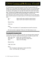
space before the comma is optional.
Most commands can be queried for their current settings by substituting the ‘?’ for the parameter
list, or by not supplying any parameters at all. For instance to request the current LED Intensity
settings:
LI ?<CR>
or
LI<CR>
This would cause the device to issue a LED Intensity Response, (the Response String format
is described in the section entitled:
“The Response String”
). The whitespace before the ‘?’ is
optional.
Commands that can supply more than one Response String per query request, or commands
that are backwards compatible with the HDS4.2 require a ‘?’ and will generate a parameter count
error if no parameters are given.
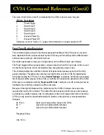
Using Bitmapped Parameters
Some commands accept “Bitmapped” parameters. These are decimal values that represent a
series of flags, or bits, that control, enable and/or disable different device operations.
Binary arithmetic is used to represent bitmapped parameters, it is assumed the reader has some
familiarity with binary arithmetic.
An example of a command that uses a bitmapped parameter is the “
XS
settings
<CR>
” com-
mand, which is defined like this:
XS
settings
<CR>
Where ‘settings’ is a bitmapped parameter:
Decimal Value
+128 +64 +32 +16 +8 +4 +2 +1
Bit Position
7
6
5
4
3
2
1
0
Name
0 CRC CSE IRJ IRS IRE FP AS
Factory Settings:
0
0
0
1
1
1
1
0
AS - 0=Master / Slave mode. 1=Asynchronous Mode.
KB - 0=Disable Front Panel.
1=Front Panel Enabled
IRE - 0=Disable IR.
1=Enable IR.
IRS - 0=Turn off IR Sensor.
1=Turn on IR Sensor.
IRJ - 0=Turn off IR Jack.
1=Turn on IR Jack.
CSE - 0=Disable CS and CRC-8 1=Append either Checksums or CRC-8 to responses.
CRC - 0=Append Checksums or, 1=Append CRC-8’s to reponses.
0
- Reserved, always set to 0.
This indicates the parameter ‘settings’ is bitmapped parameter, followed by a description of what
each bit represents.
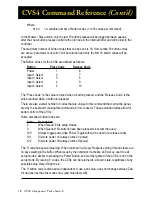
The ‘Decimal Value’ in the table’s header, refers to the values added together to create the deci-


