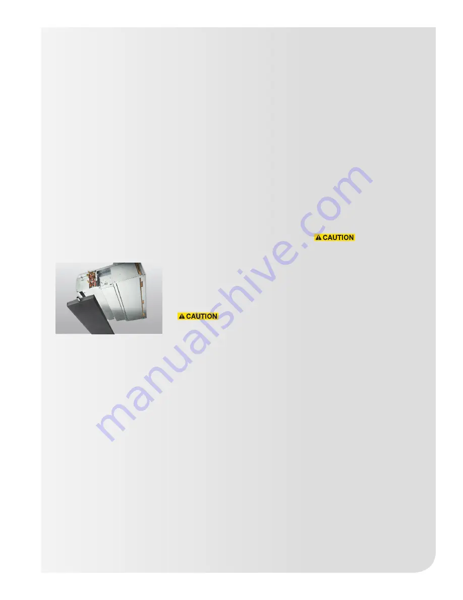
Chilled/hot water connections
27
Chilled/hot water
connections
Submittals and product literature
detailing unit operation, controls
and connections should be
thoroughly reviewed before
beginning the connection of the
various cooling and/or heating
mediums to the unit.
If required, field modifications
can be made to horizontal
hideaway models to change
coil connections from left hand
to right hand or vice versa. To
do so, remove drain pan by
undoing clips and removing from
mounting pins. Remove screws
holding sheet metal panels
below coils, rotate coil direction
and reassemble.
All shipped loose valve packages
should be installed as required
and all service valves should be
checked for proper operation.
All coil and valve package
connections are to be made with a
sweat or solder joint. Care should be
taken to assure that no components
in the valve package are subjected
to a high temperature which may
damage seals or other materials.
Many two-position electric control
valves, depending on valve operation,
are provided with a manual opening
lever. This lever should be placed
in the “open” position during all
soldering or brazing operations. In
accordance with good soldering
and brazing practices, valve bodies
should be wrapped with a wet rag to
help dissipate the heat.
If the valve package connection at
the coil is made with a union, the coil
side of the union must be prevented
from twisting during tightening to
prevent damage to the coil tubing.
Over-tightening must be avoided
to prevent distorting the union seal
surface and destroying the union,
ultimately causing a leak.
Secure the union nut hand-tight
and then tighten no more than an
additional 1/4 turn.
The inlet supply connection is
marked at the appropriate coil stub-
out with the other coil stub-out being
the outlet return connection. In the
case of field installed valve packages
and piping, the chilled water valve
package should be installed in such
a way that any dripping condensate
is captured in the drain pan/auxiliary
drip pan or alternatively, is eliminated
through the use of insulation.
Factory drip pans are field
installed and may be packaged
separately from the unit. Factory
supplied cooling coil valve
packages will be arranged over
the drain pan and/or drip pan.
After the connections are
completed, the system should
be tested for leaks. Since
some components are not
designed to hold pressure with
a gas, hydronic systems should
be tested with water. Test
pressure must not exceed 250
psig. Pressure testing should
be completed prior to sheet
rocking, finished floors, painting,
caulking, etc.
All water coils must be protected
from freezing after initial filling
with water. Even if the system is
drained, unit coils may still hold
enough water to cause damage
when exposed to temperatures
below freezing.
In the event that leaking or
defective components are
discovered, the Zehnder Rittling
Sales Representative must be
notified before any repairs are
attempted. All leaks should be
repaired before proceeding with
the installation.


