background image


Pile Reg. IT12110P00002965 - 

Share Capital € 100,000.00 fully paid up 

AR Company Reg. no. 03225010481 - REA AR no. 94189 

ISO 9001 Certified Company - Certificate no. 9151 - CNS0 - IT-17778 


Zucchetti Centro Sistemi S.p.A. - Green Innovation Division 
Via Lungarno, 248 - 52028 Terranuova Bracciolini - Arezzo, Italy  
tel. +39 055 91971 - fax. +39 055 9197515 

[email protected] - [email protected] 

– 

www.zcsazzurro.com


Ident

ific

at

ion:

 M

D

-AL

-GI

-0


R

ev

. 1

.1

 of

 16/

03/

20

21 

- A

ppl

ic

at

ion

G

ID


3PH HYD5000-HYD20000-ZSS 

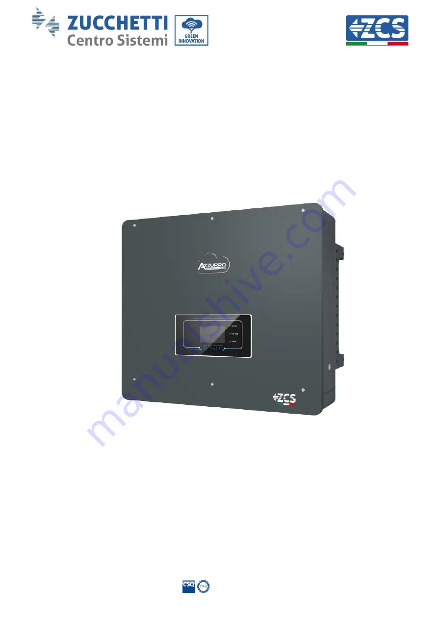
hybrid inverter 

User Manual 


Summary of Contents for Azzurro 3PH HYD5000 ZSS

Page 1: ...no 9151 CNS0 IT 17778 Zucchetti Centro Sistemi S p A Green Innovation Division Via Lungarno 248 52028 Terranuova Bracciolini Arezzo Italy tel 39 055 91971 fax 39 055 9197515 innovation zcscompany com...

Page 2: ...lation tools 18 3 5 Wall installation position 20 3 6 Assembly instructions 21 4 Electrical connections 22 4 1 Connection of protective ground cables PGND 25 4 2 Connecting the battery 27 4 2 1 Instal...

Page 3: ...s 69 6 Buttons and indicator lights 71 7 Operation 72 7 1 Before configuration follow carefully 72 7 2 Commissioning 73 7 2 1 OSD language options 74 7 2 2 Setting of date and time confirmation 74 7 2...

Page 4: ...Monitoring systems 111 11 1 External Wi Fi adapter 111 11 1 1 Installation 111 11 1 2 Configuration 112 11 1 3 Verification 121 11 1 4 Troubleshooting 123 11 2 Ethernet adapter 128 11 2 1 Installatio...

Page 5: ...r or plant Copyright statement Copyright of this manual belongs to Zucchetti Centro Sistemi S p A No part of this manual including the software etc may be copied reproduced or distributed in any form...

Page 6: ...that it is accessible at all times Recipients This manual is intended for qualified technical personnel installers technicians electricians technical support personnel or anyone who is qualified and...

Page 7: ...system can be combined with WeCo or Pylontech batteries supplied in kit form by ZCS Azzurro The basic operating scheme is shown in Figure 1 the inverter has direct access to the photovoltaic productio...

Page 8: ...refully and make sure you fully understand its contents The 3PH HYD5000 HYD20000 ZSS inverter strictly complies with the safety regulations if it is installed connected and serviced according to the i...

Page 9: ...lectronic components against violent knocks humidity vibrations etc Zucchetti Centro Sistemi S p A shall NOT be responsible for any damage or loss caused by improper installation 2 2 Assembly and main...

Page 10: ...e The inverters do not require any daily or periodic maintenance The heat exchangers and cooling fans must not be obstructed or clogged by dust dirt or other objects Before cleaning ensure that the DC...

Page 11: ...and understand the content of the symbols before installing the inverter This symbol indicates a hazardous situation which if not avoided will result in injury Risk of electric shock wait at least 5 m...

Page 12: ...he IEC 70 1 EN 60529 June 1997 standard Positive and negative polarities of DC voltage Photovoltaic and Battery This side up The 3PH HYD5000 HYD20000 ZSS inverter must always be transported handled an...

Page 13: ...gy in excess and when the photovoltaic energy is lower than that required the inverter uses the energy stored in the battery to supply current to the local load 3 1 Product overview The 3PH HYD5000 HY...

Page 14: ...25A per string e Wide battery voltage range 200 700V f Off grid output can be connected to an unbalanced load g Multi parallel AC function more flexible solution h Intelligent monitoring RS485 Wi Fi B...

Page 15: ...3 2021 Application GID 15 138 3 2 Package contents No Part Qty 1 Inverter 1 2 Bracket 1 3 PV clamp terminals 4 4 PV clamp terminals 4 5 Metal clamp terminals fixed to PV input power cables 4 6 Metal c...

Page 16: ...T input power cables 2 10 Metal clamp terminals fixed to BAT input power cables 2 11 M6 hexagonal screws 2 12 M8x80 expansion plugs to secure the bracket to the wall 4 13 AC Grid Connector 1 14 Critic...

Page 17: ...m 1 Table 3 Package contents 3 3 Requirements for the installation environment DO NOT install the 3PH HYD5000 HYD20000 ZSS on flammable material DO NOT install the 3PH HYD5000 HYD20000 ZSS in an area...

Page 18: ...can be damaged during transport Therefore check the outer packaging before installation check that the materials are not damaged In case of damage contact the dealer as soon as possible It is recomme...

Page 19: ...Crimping tool To crimp the power cables 8 Multi meter To meter the ground protection 9 Marker To mark the references 10 Tape measure To measure distances 11 Level To make sure the support is level an...

Page 20: ...e area must be tidy and convenient for installation and well ventilated to prevent overheating DO NOT place it near flammable or explosive materials The AC overvoltage of the 3PH HYD5000 HYD20000 ZSS...

Page 21: ...or paper under it to protect the housing Attention 1 Determine the position of the holes make sure the positions of the holes are level then mark them with a marker pen Use the drill to make the holes...

Page 22: ...e inverter must be installed and serviced by a professional electrician Wear protection equipment when working on high voltage high current systems such as inverters and battery systems Attention For...

Page 23: ...S Rev 1 1 16 03 2021 Identification MD AL GI 00 Rev 1 of 16 03 2021 Application GID 23 138 1 Direct insertion current sensors Figure 9 Configuration with CT current sensor 2 Meter CT sensor Figure 10...

Page 24: ...e electrode to the lithium battery connection of the positive electrode to the photovoltaic system Outdoor industrial cable for photovoltaic systems Conductor with cross section 6mm2 connection of the...

Page 25: ...D The inverter does not have a transformer therefore the positive and negative polarities of the PV array do NOT have to be grounded All the metal parts in the photovoltaic supply system that do not c...

Page 26: ...crimped OT terminal insert the M5 screw and tighten the screw at a torque of 3Nm using the hex key NB L3 is the length between the insulating layer of the ground cable the L4 curved part and the core...

Page 27: ...h battery connect them one at a time to the inverter and view the charge level on the display all the instantaneous information can be accessed by pressing the Down key from the main menu The batterie...

Page 28: ...cted in series via the cables shown in figure 4 The connection cables are supplied with the battery Figure 17 Power connector between battery modules The connector must be connected from the negative...

Page 29: ...llow the colour of the connector as a reference Figure 18 Power cable between battery modules Subsequently the external BMS must be connected to the series of battery modules Therefore the positive of...

Page 30: ...lication GID 30 138 Figure 20 Power connection positive between the BMS and first battery module Figure 21 Power connection negative between the BMS and the last battery module Finally the BMS must be...

Page 31: ...8 Figure 22 BMS Inverter power cables left inverter side power terminals centre battery side power terminals left Figure 23 BMS power connection Negative cable connected to last battery module Positiv...

Page 32: ...arranged as follows using the communication cables between battery modules Link port 1 of the BMS to link port 0 of the first battery Link port 1 of the first battery must be connected to link port 0...

Page 33: ...ng all the pins down this means the address equals 000000 Figure 27 000000 battery address For communication between the battery and inverter use the black communication cable supplied which has the B...

Page 34: ...User Manual 3PH HYD5000 HYD20000 ZSS Rev 1 1 16 03 2021 Identification MD AL GI 00 Rev 1 of 16 03 2021 Application GID 34 138 Figure 28 CAN input of the BMS Figure 29 Pin Out CAN BMS input...

Page 35: ...battery modules and the BMS must be connected as indicated in section 2 1 1 As for the connection between each tower and the inverter the two power cables and coming from the BMS will be connected to...

Page 36: ...ust be connected to the last battery BMS Inverter communication The two BMS must be set with a different address by changing the position of the dip switches as shown below Address 000000 address 0 to...

Page 37: ...ication connector supplied with the inverter see figure 18 Connect the cable in position 5 white blue wire to position 8 of the communication connector supplied with the inverter see figure 18 Connect...

Page 38: ...of 16 03 2021 Application GID 38 138 PIN Invert er Battery communication Notes 7 CAN H blue wire Communication with the BMS of the lithium battery the CAN of the inverter adapts to the BMS of the lith...

Page 39: ...1 of 16 03 2021 Application GID 39 138 4 2 2 Installing WeCo batteries 4 2 2 1 Only one battery tower connected Figure 36 Single battery tower Each tower consists of a HV BOX connected in series to m...

Page 40: ...tor must be connected from the negative input of the first battery to the positive input of the second one From here the negative input must be connected to the positive input of the third module cont...

Page 41: ...bsequently the HV BOX must be connected respecting the and polarity as it is powered by the batteries themselves Therefore the positive of the HV BOX must be connected to the positive of the first bat...

Page 42: ...nections between the HV BOX and the inverter the HV BOX module allows the connection of both channels coming from the inverter if properly set from the inverter LCD the battery column will be able to...

Page 43: ...the second last battery to CAN A of the last battery LINK B of the second last battery to LINK A of the last battery As regards the positioning of the dip switches of the battery tower it is necessary...

Page 44: ...BOX and first battery module connection between battery modules connection between second last and last battery module in the series HV BOX and Inverter communication Figure 43 HV BOX configuration I...

Page 45: ...ery tower Power connections The power cables in each tower between the battery modules and HV BOX must be connected as indicated in section 2 1 1 As for the connection between each tower and the inver...

Page 46: ...CAN A of the first battery LINK of the HV BOX to LINK A of the first battery CAN B of the first battery to CAN A of the second battery LINK B of the first battery to LINK A of the second battery CAN...

Page 47: ...be connected by populating the CAN2 A input with the Inverter HV BOX communication cable The other end in which only the orange and white orange wires are present must be wired to the quick connect CO...

Page 48: ...Application GID 48 138 Figure 48 COM port connection PIN Inverter Battery communication Notes 7 CAN H white orange wire Communication with thee HV BOX of the lithium battery the CAN of the inverter a...

Page 49: ...Table 6 The steps are the same as for the battery Before removing the positive and negative connectors make sure that the DC circuit breaker is open Danger 4 4 Load connection Procedure 1 Select the...

Page 50: ...rminal clamping 4 5 Grid connection The inverter is equipped with an integrated unit for monitoring the residual current when the inverter detects that the residual current exceeds 300mA the connectio...

Page 51: ...03 2021 Application GID 51 138 4 Connect the wire to the terminal according to the identification on the terminal Figure 54 Connecting the wire to the terminal 5 Connect the terminal to the machine po...

Page 52: ...ication GID 52 138 5 External communication 5 1 USB Wi Fi Figure 56 External Wi Fi connection Table 57 Interface description PIN Definition Function Notes 1 GND S Power Supply USB The USB power supply...

Page 53: ...le into the RJ45 connector The pins of the logical interface are defined according to the different standard requirements a Logical interface according to the VDE AR N 4105 standard 2018 11 necessary...

Page 54: ...2 Input contact relay 2 K2 Output relay 2 3 L3 Input contact relay 3 K3 Output relay 3 4 L4 Input contact relay 4 K4 Output relay 4 5 NC Not connected Not connected 6 G GND Relay common node 7 NC Not...

Page 55: ...tput relay 1 2 NC Not connected Not connected 3 NC Not connected Not connected 4 NC Not connected Not connected 5 NC Not connected Not connected 6 G GND K1 Output relay 1 7 NC Not connected Not connec...

Page 56: ...n MD AL GI 00 Rev 1 of 16 03 2021 Application GID 56 138 5 3 COM Communication Multifunction Figure 61 COM interface Refer to Figure 6below for the RS485 connection if you want cascade monitoring of t...

Page 57: ...th BMS of the lithium battery 8 CAN0_L CAN negative polarity 9 GND S BMS communication GND 10 485TX0 RS485 differential signal 11 485TX0 RS485 differential signal 12 GND S GND signal Lead acid battery...

Page 58: ...CT sensors for measuring the currents exchanged with the grid is shown in the figure below 5 4 1 Direct connection of CT sensors In the case of direct connection of the CT sensors use the dedicated co...

Page 59: ...nsors according to the direction on the sensor arrow Figure 65 Reference to sensor direction If it is necessary to extend the sensor connection cables use UTP network cables or FTP grid cables if ther...

Page 60: ...ry to use the Meter in addition to the sensors as shown in the figure Make sure to position the probes so that each toroid reads only the current flows relating to the exchange To do this it is recomm...

Page 61: ...terminals of the S phase sensor must be connected to PIN 4 red wire and PIN 6 black wire The terminals of the T phase sensor must be connected to PIN 7 red wire and PIN 9 black wire Position the senso...

Page 62: ...ignal 24 Communication with Meters 6 RS485 differential signal 25 Table 13 Interface description Figure 71 Connection of Meter serial port NOTE For distances greater than 100 metres between the Meter...

Page 63: ...to its inputs but also the power produced by external photovoltaic panels This is achieved by connecting a second Meter in a suitable position that allows reading the entire production of the photovol...

Page 64: ...vice in read mode on exchange enter the settings menu as shown below 1 Press SET and the word CODE will appear 2 Press SET again and the number 600 will appear 3 Enter the number 701 a From the first...

Page 65: ...In case of error press SET until the number relating to thousands is highlighted and then press until only the number 1 appears at this point repeat the above procedure iii Press ESC to confirm and t...

Page 66: ...indicated a CT i Press SET to enter the menu ii Write 40 1 From the first screen where the number 1 appears press the key several times to write the number 10 2 Press SET once to move the cursor left...

Page 67: ...oltaic production Switch on loads of more than 1 kW for each of the three phases of the system Stand in front of the meter and use the keys to scroll through the items and ESC to go back checking that...

Page 68: ...value Pt is in line with the value shown on the inverter s display Checking the Meter on Production In case of meter on production repeat the above steps 1 Check the Power Factor as described in the...

Page 69: ...lave 1 Inverter Link port 0 of Slave 2 Inverter Link port 3 of Slave 2 Inverter Link port 0 of Slave 3 Inverter Link port 1 of Slave n 1 Inverter Link port 0 of Slave n Inverter 2 If the inverters con...

Page 70: ...s PIN Definition Function Notes 1 IN_SYN0 Signal synchronisation 0 The high signal level is 12 V 2 CANL CAN negative polarity 3 SYN_GND0 Signal synchronisation GND0 4 CANH CAN positive polarity 5 IN_S...

Page 71: ...Back to go back to the previous screen or enter the main page Up to move up the menu or for the 1 function Down to move down the menu or for the 1 function OK to select the current option of the menu...

Page 72: ...inverter s LOAD port and the critical load with the automatic switch OFF 7 The communication cable of the lithium battery must be correctly connected 7 1 Before configuration follow carefully IMPORTAN...

Page 73: ...renamed according to the country selected on the website download them to a USB stick and import them 4 Setting of input channel Default order BAT1 BAT2 PV1 PV2 5 Setting of battery parameters The de...

Page 74: ...e values on the USB stick beforehand To enable this option contact Zucchetti Centro Sistemi S p A Code Region Code Region 00 00 Germany VDE4105 18 00 EU EN50438 01 BDEW 01 EN50549 02 VDE0126 19 00 IEC...

Page 75: ...3 108 00 Lithuania Table 17 List of country codes 7 2 4 Setting of input channel Input Channel Config Input Channel1 Bat input 1 Up Down Bat input 2 OK Not use Input Channel2 Bat input 1 Up Down Bat i...

Page 76: ...put channel 3 PV input 1 Input channel 4 PV input 1 7 2 5 Setting of battery parameters Single Pylontech battery tower Single WeCo battery tower Double PYLON WECO battery tower Battery identification...

Page 77: ...Curve Scan Disable Logic interface Disable Table 18 Default values for other settings 7 3 Main menu Figure 78 Main menu interface From the main interface press the Down key to enter the page with the...

Page 78: ...Current T A Frequency Hz Battery Information 1 Batt1 V V Batt1 Curr A Batt1 Power KW Batt1 Temp Batt1 SOC Batt1 SOH Down Batt1 Cycles T Battery Information 2 Batt2 V V Batt2 Curr A Batt2 Power KW Bat...

Page 79: ...p PV Information PV1 Voltage V PV1 Current A PV1 Power KW PV2 Voltage V PV2 Current A PV2 Power KW Inverter Temp From the main interface press the Back key to enter the main menu which has the followi...

Page 80: ...6 Input Channel Config 7 EPS Mode 8 Communication Addr 9 Set ForceChargeTime 1 Language settings 1 Language Settings OK 1 OK 2 English 3 Italian 4 2 Time Set the system time for the inverter 2 Time OK...

Page 81: ...tion kW with P 100W the inverter does not charge or discharge the battery Figure 85a If the PV generation kW consumption kW the power surplus is stored in the battery Figure 85b Figure 79 Inverter dis...

Page 82: ...ic system cannot effectively charge the battery it may be necessary to set a date range for recharging the battery from the grid once this range has been set the inverter will operate in automatic mod...

Page 83: ...e Start 14 h 00 m Discharge End 16 h 00 m Discharge Power 02500 W Passive Use For more detailed information on passive operation please contact Zucchetti Centro Sistemi S p A 5 Self test 5 Autotest OK...

Page 84: ...MD AL GI 00 Rev 1 of 16 03 2021 Application GID 84 138 Wait Testing 27 S1 Wait Test 27 S1 OK Wait Testing 27 S2 Wait Test 27 S2 OK Wait Testing 81 S1 Wait Test 81 S1 OK Wait Testing 81 S2 Wait Test 8...

Page 85: ...Press Ok OK self test Press Down 59 S1 threshold 253V 900ms Press Down 59 S1 228V 902ms Press Down 59 S2 threshold 264 5V 200ms Press Down 59 S2 229V 204ms Press Down 27 S1 threshold 195 5V 400ms Pres...

Page 86: ...100ms Press Down 81 S2 49 9Hz 107ms Press Down 81 S1 threshold 49 5Hz 100ms Press Down 81 S1 50 0Hz 105ms Press Down 81 S2 threshold 47 5Hz 100ms Press Down 81 S2 50 1Hz 107ms 6 Configuration of input...

Page 87: ...OK 2 Disable EPS Mode If the PV generation kW consumption kW with P 100W the inverter charges the battery Figure 88a If the PV generation kW consumption kW the inverter does not charge or discharge t...

Page 88: ...AL GI 00 Rev 1 of 16 03 2021 Application GID 88 138 Figure 83 Display with EPS in operation 2 8 Communication address 8 Communication Addr OK 1 Communication Addr OK 2 Baud Rate OK 9 Setting of force...

Page 89: ...urve Scan 5 DRM0 Control 6 Factory Reset 7 Parallel settings 8 Bluetooth Reset 9 CT Calibration 1 Battery parameters A Internal BMS 1 Battery Parameters OK 1 Battery Type 5 Max Charge A 2 Battery Capa...

Page 90: ...f Discharge OK Depth of Discharge 50 EPS of Depth of Discharge 80 EPS Restore Depth 20 2 Battery active Function to be implemented 3 Anti Reflux The Anti Reflux Control mode can be enabled to limit th...

Page 91: ...le or disable logic interfaces Refer to the chapter on the connections between logic interfaces Section 5 page 52 4 Logic interface Control OK Enable OK Disable OK 6 Reset factory settings 5 Factory R...

Page 92: ...the sensors have been connected the CT Calibration function in the advanced settings of the device can be used to allow the system to correctly read the current flows In order for the inverter to per...

Page 93: ...gh the main menu to monitor the details of the event history in real 3 Event List OK 1 Current Event List OK ID042 IsoFault 2 History Event List 2 History Event List OK 1 ID001 2020 4 3 14 11 45 OK 1...

Page 94: ...2 Hardware Version Power Level Country Energy Storage Mode Down Inverter Info 3 Input Channel1 Input Channel2 Input Channel3 Input Channel4 Down Inverter Info 4 RS485 Address EPS Mode IV Curve Scan A...

Page 95: ...ry Info OK Battery1 2 info 1 Battery Type Battery Capacity Depth of Discharge Max Charge A Down Inverter1 2 Info 2 Over V Protection Max Charge V Max Discharge A Min Discharge V Down Inverter1 2 Info...

Page 96: ...of 16 03 2021 Application GID 96 138 UFP 2 Down Safety Param 3 OVP 10mins 7 3 5 Energy statistics 3 Energy Statistics OK Today PV KWH Load KWH Export KWH Import KWH Charge KWH Discharge KWH Down Month...

Page 97: ...WH 7 3 6 Software Update The 3PH HYD5000 HYD20000 ZSS inverters offer the possibility to update the system via a USB stick for maximising the inverter s performance and preventing any operating errors...

Page 98: ...pport service USB Fault MDSP File Error SDSP File Error ARM File Error Update DSP1 Fail Update DSP2 Fail Update ARM Fail Table 19 Software update errors 5 After completing the update close the DC swit...

Page 99: ...YD5000 HYD20000 ZSS Rev 1 1 16 03 2021 Identification MD AL GI 00 Rev 1 of 16 03 2021 Application GID 99 138 8 Technical specifications 8 1 Technical data 3PH HYD5000 HYD8000 ZSS TECHNICAL DATA HYD500...

Page 100: ...nual 3PH HYD5000 HYD20000 ZSS Rev 1 1 16 03 2021 Identification MD AL GI 00 Rev 1 of 16 03 2021 Application GID 100 138 8 2 Technical data 3PH HYD10000 HYD20000 ZSS TECHNICAL DATA HYD10000 HYD15000 HY...

Page 101: ...User Manual 3PH HYD5000 HYD20000 ZSS Rev 1 1 16 03 2021 Identification MD AL GI 00 Rev 1 of 16 03 2021 Application GID 101 138...

Page 102: ...h Are the input and output connections in good condition Are the configuration and settings correct for this type of installation Are the communication system and display free of damage If all these r...

Page 103: ...ter obtaining the approval of the local grid operator ID003 GridOFP The grid frequency is too high ID004 GridUFP The grid frequency is too low ID005 GFCI Loss of charge Internal inverter errors Switch...

Page 104: ...unication error AC ID035 SChip_Fault Chip error DC ID036 MChip_Fault Chip error AC ID037 HwAuxPowerFaul t Auxiliary power error ID041 RelayFail Relay detection error ID042 IsoFault Low impedance isola...

Page 105: ...2 ID059 TempFault_Inv1 Module 1 temperature protection ID060 TempFault_Inv2 Module 2 temperature protection ID061 TempFault_Inv3 Module 3 temperature protection ID065 VbusRmsUnbalanc e RMS bus voltage...

Page 106: ...nical support ID072 SwBusRmsOVP Software RMS overvoltage protection of the DC bus ID073 SwBusInstantOVP Software instantaneous overvoltage protection of the DC bus ID081 SwBatOCP Battery software over...

Page 107: ...ture limits and away from direct sunlight Check that the inverter has been installed according to the instructions in the manual ID114 FreqDerating AC frequency is too high Make sure that the grid fre...

Page 108: ...nrecoverRelayFa il Permanent relay error ID141 unrecoverVbusUn balance Permanent unbalanced bus voltage error ID145 USBFault USB error Check the USB input of the inverter ID146 WifiFault WiFi error Ch...

Page 109: ...gging ID169 FanFault1 Fan1 error Check whether fan 1 of the inverter is working properly ID170 FanFault2 Fan2 error Check whether fan 2 of the inverter is working properly ID171 FanFault3 Fan3 error C...

Page 110: ...een 25 and 60 C 10 4 Disposal Zucchetti Centro Sistemi S p a is not liable for the disposal of the equipment or parts thereof that does not take place according to the regulations and standards in for...

Page 111: ...monitor the inverter the RS485 communication address must be set to 01 directly from the display Installation tools Cross screwdriver External Wi Fi adapter 1 Switch off the inverter following the pr...

Page 112: ...the Wi Fi modem Tools required for configuration Smartphone PC or tablet Go to front of the inverter and search for the Wi Fi network using a smartphone PC or tablet making sure that the signal from t...

Page 113: ...t and Android smartphone right Note Disconnect from any Wi Fi networks to which you are connected by removing automatic access Figure 87 Disabling automatic reconnection to a network 2 Connect to a Wi...

Page 114: ...droid smartphone right 3 If you are using a second generation Wi Fi adapter you will be prompted for a password to connect to the inverter s Wi Fi network Use the password found on the box or on the W...

Page 115: ...is not able to provide internet access confirm to maintain the Wi Fi connection even if the internet is not available Figure 91 Screen indicating that the Internet cannot be accessed 4 Open a browser...

Page 116: ...for accessing the web server to configure the Wi Fi adapter 5 The status screen will open showing the logger information such as the serial number and firmware version Check that the Inverter Informa...

Page 117: ...left hand column 7 In the new screen that opens select the Wi Fi network to which you want to connect the Wi Fi adapter making sure that the Received Signal Strength Indicator RSSI is greater than 30...

Page 118: ...Fi network Wi Fi modem clicking on Show Password to make sure it is correct the password should not contain special characters and spaces Note During this step the system is not able to ensure that th...

Page 119: ...ion MD AL GI 00 Rev 1 of 16 03 2021 Application GID 119 138 Figure 95 Screen for entering the password of the wireless network 2 9 Click Next again without ticking any of the options relating to the s...

Page 120: ...configuration screen 4 11 At this point if the configuration of the adapter is successful the last configuration screen will appear and the telephone or PC will unpair from the inverter s Wi Fi networ...

Page 121: ...Fi network in the list will confirm the successful configuration of the Wi Fi adapter Figure 99 Wi Fi network search on Smartphone iOS and Android Access point of the Wi Fi adapter is no longer visib...

Page 122: ...ashing on Figure 101 Initial status of LEDs 2 Final status NET left LED steady on COM central LED steady on READY right LED flashing on Figure 102 Final status of LEDs If the NET LED does not light up...

Page 123: ...n The adapter can only be reset when the inverter is switched on Figure 103 Reset button on the Wi Fi adapter 11 1 4 Troubleshooting Status of LEDs present on the adapter 1 Irregular communication wit...

Page 124: ...hand corner of the inverter s display steady or flashing Figure 105 Icons on the display of LITE single phase inverters left and three phase or hybrid inverters right Restart the adapter Press the res...

Page 125: ...hat data between the router and server is not being transmitted correctly In this case it is advisable to carry out checks at the router level in order to ensure that there are no obstructions on the...

Page 126: ...e connection verify that the 3G LTE network is active by going to Settings Mobile Phone and making sure that the Voice and data option is set to 5G 4G or 3G To enter the iOS settings menu click the gr...

Page 127: ...choose the one activated by the smartphone and then enter the password associated with it which can be changed from the personal hotspot settings If at the end of configuration Connected appears next...

Page 128: ...ommunication address must be set to 01 directly from the display Installation tools Cross screwdriver Ethernet adapter Shielded network Cat 5 or Cat 6 crimped with RJ45 connectors 1 Switch off the inv...

Page 129: ...inside the device 4 Connect the Ethernet adapter to the appropriate port making sure to follow the direction of the connection and ensure correct contact between the two parts a b Figure 111 Insertin...

Page 130: ...l 7 Unlike Wi Fi cards the Ethernet adapter does not need to be configured and starts transmitting data shortly after the inverter is switched on 11 2 2 Verification Wait two minutes after installing...

Page 131: ...the adapter 1 Irregular communication with inverter NET left LED steady on COM central LED off SER right LED flashing on Figure 115 Irregular communication status between the inverter and adapter Che...

Page 132: ...or is correctly crimped 2 Irregular communication with remote server NET left LED off COM central LED on SER right LED flashing on Figure 116 Irregular communication status between the adapter and rem...

Page 133: ...et to 01 directly from the display 11 3 1 Installation Installation must be carried out for all inverters compatible with the adapter However the procedure is quicker and easier as there is no need to...

Page 134: ...tion of the connection and ensure correct contact between the two parts Secure the 4G adapter by tightening the two screws inside the package a b Figure 118 Inserting and securing the 4G adapter 4 Swi...

Page 135: ...atus of LEDs present on the adapter 1 Initial status NET left LED off COM central LED flashing on SER right LED flashing on Figure 119 Initial status of LEDs 2 Registration NET left LED flashes rapidl...

Page 136: ...s set on the inverter Enter the main menu with the ESC key first key on the left go to System Info and press ENTER to enter the submenu Scroll down to the Modbus address parameter and make sure it is...

Page 137: ...ignal is present in the installation location the adapter uses the Vodafone network for 4G transmission if this network is not present or the signal is weak the SIM will use a different network or wil...

Page 138: ...tification MD AL GI 00 Rev 1 of 16 03 2021 Application GID 138 138 12 Warranty terms and conditions To view the Warranty Terms and Conditions offered by ZCS Azzurro please refer to the documentation i...

Reviews: