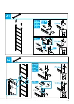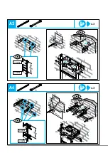
Exit step
Within the scope of EN ISO 14122 Part 4 and DIN 14094-1, the clearance between the step
and machine must not exceed 75 mm.
• Where necessary, adjust the clearance on site.
Security door for maintenance and escape ladders
• Recommendation: the security door should be assembled by at least two persons.
• After opening, secure the security door against closing unintentionally.
Rest platform
• Attach the opening cord to the fixed ladder in such a way that safe exit is ensured.
• If the rest platform is used as an end platform: secure the rest platform with a screw
to prevent accidental opening.
Emergency exit ladder
– Recommendation: the emergency exit ladder should be assembled by at least
two persons.
In the area of the descending ladder:
– The end of the ladder system must not be located above entrances or exits to
the building.
– The end of the descending ladder must be located on a level surface of sufficient
load-bearing capacity.
– Take appropriate protective measures, e. g. set up a keep-out area below
the ladder system.
• Perform the following function test to check that the emergency exit ladder can be
extended without obstructions:
– Guide the emergency exit ladder down with a rope. The ladder must extend
without obstruction.
– Pull the emergency exit ladder up and fix it in position.
Exit and extension platform
Observe the following point in the case of platform systems comprising an exit platform
and several extension platforms:
• The exit platform must always be at the end of the platform configuration.
Spacer segment
To improve the heat conductivity properties of the spacer segment, the cavity can be filled
with PU foam or similar material.
Safety cage
A back guard segment consists of two hoops and five straps.
Two back guard segments consist of three hoops and ten straps.
Safety barrier
Safety barriers can be installed together with the following products: straight stile
extension (43243/44243), angled stile extension (43049/44049), landing with crossover
(41181/42181/43181/44181)
Safety rails
• The safety rail must be connected to the stile extensions.
• The safety rail must be ballasted before use.
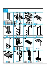
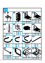
A11
B1 B6
B2
B3
B8-B9
B11
C1-C4
C5-C6
C7-C9
41
en
Summary of Contents for 41286
Page 61: ...4 3 B2 1 2 13 17 5 Nm 2 2 1 M8 M8 M8x65 2 1 3 17 5 Nm 4 3 B3 1 2 1 3 61...
Page 63: ...4 3 B5 1 2 M8 M8 17 5 Nm M8 M8 13 2x 17 5 Nm 1 1 2 2 4 3 B6 1 2 M8 M8 17 5 Nm 1 2 13 2x A19 63...
Page 64: ...4 3 B7 1 M8 M8 17 5 Nm 2 13 2x...
Page 68: ...4 3 B12 1 2 3 1 2 13 17 5 Nm 0...
Page 72: ...4 3 C8 13 2x 1 2 10x 1 2 3 4 4 3 C7 13 2x 1 2 1 1 2 4 3 17 5 Nm 5 5 6 17 5 Nm...
Page 73: ...4 3 C9 10 73...

